Print Vendor Instructions Paper Size: How to use this file Operator’s Manuals • 11x17 • Body - 50 lbs brilliant white offset or equivalent • Cover - on pre-printed two tone “Swash” stock. Press: • Body - 1 color, 2-sided • Cover - 1 color, 1 sided Bindery: • Saddle stitch, face trim *if too thick for saddle stitch, tape bind Covers: • FRONT COVER is present at the beginning of the file. • BACK COVER is the page immediately after the front cover.
THIS PAGE INTENTIONALLY BLANK (FOR PLACEMENT ONLY - DO NOT PRINT)
OPERATOR’S MANUAL Intermediate Snowthrower Models 555 Models Mfg. No. 1693980 1693981 Description 555M, 5HP Snowthrower, Manual Start 555M, 5HP Snowthrower, Manual Start (Export) 755 Models Mfg. No. 1693982 1693983 Description 755M, 7HP OHV Snowthrower, Manual Start (Export) 755E, 7HP OHV Snowthrower, Electric Start 860 Models Mfg. No.
MANUFACTURING, INC. 500 N Spring Street / PO Box 997 Port Washington, WI 53074-0997 www.simplicitymfg.com © Copyright 2003, Simplicity Manufacturing, Inc. All Rights Reserved. Printed in USA.
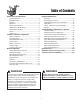
Table of Contents Safety Rules & Information Regular Maintenance General Operation ..................................................2 Slope Operation ......................................................2 Children...................................................................3 Emissions................................................................3 Service & Maintenance ...........................................3 ANSI B71.3-1995 Warnings ....................................
Safety Rules & Information Read these safety rules and follow them closely. Failure to obey these rules could result in loss of control of unit, severe personal injury or death to you, or bystanders, or damage to property or equipment. The triangle in text signifies important cautions or warnings which must be followed. GENERAL OPERATION • Read, understand, and follow all instructions in the manual and on the unit before starting.
Safety Rules EMISSIONS CHILDREN • Engine exhaust from this product contains chemicals known, in certain quantities, to cause cancer, birth defects, or other reproductive harm. • Look for the relevant Emissions Durability Period and Air Index information on the engine emissions label. Tragic accidents can occur if the operator is not alert to the presence of children. Children are often attracted to the unit and the operating activity. Never assume that children will remain where you last saw them.
Safety Rules ANSI B71.3-1995 WARNINGS Training 1. Read the operating and service instruction manual carefully. Be thoroughly familiar with the controls and the proper use of the equipment. Know how to stop the unit and disengage the controls quickly. 2. Never allow children to operate the equipment. Never allow adults to operate the equipment without proper instruction. 3. Keep the area of operation clear of all persons, particularly small children and pets. 4.
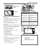
Identification Numbers SA M North American Models PL E 169XXXX Serial No.: kW: Engine RPM LpA: Vibration: XXXXX XXX XXXX XXX dB(A) XXX m/s² SA Mfg. No.: 2002 dB(A) CE Models M PRODUCT REFERENCE DATA PL Model Description Name/Number Simplicity Mfg. Inc. Port Washington, WI USA 53074-0997 E When contacting your authorized dealer for replacement parts, service, or information you MUST have these numbers.
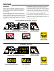
Safety Decals GENERAL All WARNING, CAUTION, and instructional messages on your unit should be carefully read and obeyed. Personal bodily injury can result when these instructions are not followed. The information is for your safety and it is important. The safety decals below are on your unit. This unit has been designed and manufactured to provide you with the safety and reliability you would expect from an industry leader in outdoor power equipment manufacturing.
CE Safety Icons & Compliance Specs Warning: Read Operator’s Manual. Warning: Dismemberment. Read and understand the Operator’s Manual before using this machine. This machine can amputate limbs. Keep bystanders and children away when engine is running. Danger: Thrown Objects. Danger: Dismemberment. This machine is capable of throwing objects and debris. Keep bystanders away. The auger can amputate limbs. Keep hands and feet away from auger and rotating parts. Warning: Remove Key Before Servicing.
Features, Controls, & Operation ALL MODELS BRIGGS & STRATTON MODELS 1,2..
Features & Controls CONTROL LOCATIONS Please take a moment and familiarize yourself with the name, location, and function of these controls so that you will better understand the safety and operating instructions provided in this manual. The information below briefly describes the function of individual controls. Starting, stopping, and driving require the combined use of several controls applied in specific sequences.
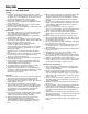
Engine Controls STARTING CONTROLS Tecumseh L-Head Models See Figures 1 and 2 for the following instructions. Units with Optional Electric Start B A C A. Electric Start Button - The Electric Start Button (A) activates an electric starter mounted to the engine, eliminating the need to pull the starter handle. The Electric Start Button operates on 120 Volts AC, which is provided by connection to the extension cord provided with units equipped with this feature.
Controls GROUND SPEED CONTROLS C A. Speed Selector - This lever (A, Figures 4 & 5) is used to set the ground speed of the snowthrower. A B D The snowthrower has five forward speeds, 1–5, and two reverse speeds, 1–2. No neutral position or gate is required, since the traction drive design automatically provides "neutral" (no forward or reverse movement), whenever the Drive Control is released. B.
Operation GENERAL OPERATION WARNING CHECKS BEFORE EACH START-UP This unit is a “two-stage” snowthrower. 1. Make sure all safety guards are in place and all nuts, bolts and clips are secure. The first stage is the auger, which feeds the snow back into the impeller housing. The second stage is the impeller, which throws the snow out the discharge chute. If bodily contact is made with the auger or impeller when they are rotating, severe personal injury will occur. 2. Check the engine oil level.
Operation STARTING THE ENGINE Tecumseh L-Head Models 1. Turn the fuel valve (B, Figure 6) to the ON position. B A 2. Insert the Engine Key (F) into the Engine Key slot and push fully in to the RUN position. C 3. Move the Throttle Lever (E) fully up to the FAST position. D 4. Fully close the Choke (G) if engine is cold. (Do not choke a warm engine.) 5. Push the Primer Button (D) two times if engine is cold. (Do not prime a warm engine.) E F 6.
Operation OPERATING THE SNOWTHROWER C 1. Rotate the discharge chute to the desired direction. A D B 2. Set the Speed Selector to the desired forward speed. 3. Fully press and hold the Auger Control (C, Figure 7) on the right-hand grip to begin auger rotation. To disengage the auger, completely release the lever. 4. Fully press and hold the traction Drive Control lever (B, Figure 7) on the left-hand grip to engage the traction drive and begin moving the snowthrower.
Operation DEFLECTOR Chute Deflector Knob The distance of the discharged snow is mainly controlled by the position of the deflector (Figure 9). (Engine speed also affects distance of discharge.) The more the deflector is tilted UP, the farther snow will be thrown. Loosen the deflector knob, tilt the deflector UP or DOWN, and then retighten the knob when the desired angle has been chosen. Chute Deflector Figure 9.
Operation FREE-WHEELING AND TRACTION DRIVE LOCK For easy turning when pushing the snowthrower, you can disengage the traction drive at one or both wheels by using the Traction Lock Pins (See Figures 11 & 12). Klik-Pin In OUTER Hole 1. Turn the unit off, remove the Engine Key, and disconnect the spark plug wire. 2. To DISENGAGE the traction drive lock, insert the Traction Lock Pin through the outer hole in the axle. (See Figure 11). 3.
Regular Maintenance SCHEDULE CARE REQUIRED FREQUENCY LUBRICATION Check auger gear case lubrication.** 25 Hours Simplicity Winter Weight Worm Gear Oil Lubricate snowthrower. 10 Hours 10W Oil and Grease Check tire pressure. Monthly N/A Change engine oil.*✛ 50 Hours✛ See Engine Manual Yearly See Engine Manual 4-6 Hours N/A Yearly Lithium Grease 10 Hours 10W Oil Clean or replace spark plug.
Maintenance A C B Figure 15. Drive Area Lubrication Points (Bottom Cover Removed) A. Drive Disc C. Hex Shaft B. Frication Disc Figure 16. Snowthrower General Lubrication Points LUBRICATION General: All moving metal parts should be oiled where contact is made with other parts. Keep oil and grease off belts, pulley grooves, drive disc, and friction disc. Auger Shaft: There are two grease fittings on the auger shaft (Figure 16). Wipe the fittings clean and apply grease, using a grease gun.
Storage TEMPORARY STORAGE (30 DAYS OR LESS) WARNING Never store the unit, with gasoline in engine or fuel tank, in a heated shelter or in enclosed, poorly ventilated enclosures. Gasoline fumes may reach an open flame, spark or pilot light (such as a furnace, water heater, clothes dryer, etc.) and cause an explosion. Remember, the fuel tank will still contain some gasoline, so never store the unit indoors or in any other area where fuel vapor could travel to any ignition source.
Troubleshooting, Adjustment, & Service TROUBLESHOOTING WARNING Before performing any adjustment or service to snowthrower, stop the engine and wait for moving parts to stop. Remove the key. To prevent accidental starting, disconnect the spark plug wire and fasten away from the plug. This section provides troubleshooting and service instructions. Locate the problem and check the possible cause/remedy in the order listed. Also, refer to the engine manufacturer’s Owner’s Manual for additional information.
Troubleshooting PROBLEM Auger rotates, but snow is not thrown far enough POSSIBLE CAUSE REMEDY 1. Chute deflector too low. 1. Adjust deflector as necessary. 2. Engine speed too slow. 2. Set speed to full throttle. 3. Ground speed too fast. 4. Snowthrower discharge chute clogged. 3. Use slower Speed Selector setting. 4. STOP engine and REMOVE the key. DISCONNECT the spark plug wire. Clear auger using a narrow board. See warning in SAFETY RULES. 5. Auger belt loose or worn. 5.
Adjustments SPEED SELECTOR PIVOT ADJUSTMENT A The Speed Selector is factory set for optimal performance at each forward and reverse speed setting. However, if drive system components have been replaced, adjustment may be necessary. Adjust as follows: 1. Move the ground speed control (A, Figure 18) fully forward. B 2. Loosen the hardware (B) securing the upper and lower shift rods. C 3. Push the lower rod (C) down fully (into the housing). 4.
Adjustments DISCHARGE CHUTE WORM ASSEMBLY ADJUSTMENT Discharge Chute If the Discharge Chute becomes difficult to rotate or begins to operate erratically, the Worm Assembly may require adjustment: Discharge Chute Worm Assembly 1. Loosen the adjustment screw under the Worm Assembly mounting area (Figure 20). 2. Slide the Worm Assembly in or out to provide smooth engagement between the worm wire and the slots in the base of the Discharge Chute. 3.
Adjustments AUGER DRIVE CLUTCH ROD ADJUSTMENT The auger drive clutch rod should be adjusted so that there is no slack in the rod when moved slightly from side to side. To adjust tension on the rod: Auger Drive Clutch Rod 1. Loosen adjustment hex nuts (Figure 22). 2. Tighten top hex nut while holding rod. Tighten just until slack in rod is removed. Be careful not to move idler rod lever when adjusting clutch rod tension. 3. Tighten lower hex nut securely.
Adjustments DRIVE BELT ADJUSTMENT (Continued) If the auger drive slips (auger slows or doesn't rotate normally while blowing snow), or stays engaged when the control is disengaged — and the auger clutch rod has been properly adjusted — the auger drive belt may be out of adjustment. WARNING Auger Control Belt Cover Auger must NOT rotate unless the Auger Control lever has been depressed. Proper Auger Drive Belt adjustments stop the auger within 5 seconds after the Auger Control is disengaged.
Adjustments & Service DRIVE BELT ADJUSTMENT (Continued) WARNING Adjusting Auger Belt Guide Failure to properly adjust the Auger Belt Guide may cause auger to rotate when Auger Control has not been depressed. 1. With the Auger Control still fully depressed, adjust the Auger Belt Guide so that there is a 1/64” gap (1/32” Maximum) between the end of the guide and the belt (Figure 27), making certain the guide is NOT putting pressure on the belt. 2.
Service DRIVE BELT REPLACEMENT (Cont.) WARNING Auger Drive Belt Replacement Do not go near the discharge chute or auger when the engine is running. Do not run the engine with any cover or guard removed. 1. Remove gas from fuel tank and run engine until it stops running from lack of fuel. 2. Disconnect spark plug wire and fasten it away from the spark plug. Auger Drive Pulley 3. Remove belt cover (See Figure 24). 4. Loosen auger belt guide and slide belt off engine pulley and away from idler pulley.
Service ROLLER CHAIN REPLACEMENT NOTE: This procedure does not apply to models that use an “endless” chain. 1. Remove gas from fuel tank and run engine until it stops running from lack of fuel. 2. Disconnect spark plug wire and fasten it away from the spark plug. 3. Tilt the snowthrower forward and carefully rest unit on the auger end. 4. Rotate the wheel to locate the roller chain master link. 5. Remove the keeper link, master link and chain. 6. Install new chain and master link as shown in Figure 30. 7.
Specifications NOTE: Specifications are correct at time of printing and are subject to change without notice. * Actual sustained equipment horsepower will likely be lower due to operating limitations and environmental factors. ENGINE: CHASSIS: 5 HP* Tecumseh Wheels Spout Rotation Impeller Drive System Make Model Horsepower Displacement Oil Capacity Tecumseh Snow King 5 @ 3600 rpm 11.88 Cu.
Replacement Parts & Accessories REPLACEMENT PARTS TECHNICAL MANUALS Replacement parts are available from your authorized dealer. Always use genuine Simplicity Service Parts. Additional copies of this manual are available, as well as fully illustrated parts lists. These manuals show all of the product’s components in exploded views (3D illustrations which show the relationship of parts and how they go together) as well as part numbers and quantities used.