N ep o ro t fo du r ct io n OPERATOR’S MANUAL Hydro Cut Series 13HP Walk-Behind Mower R Mfg. No.
N ep o ro t fo du r ct io n R THIS PAGE INTENTIONALLY BLANK
Table of Contents Safety Rules & Information ............................... 2 Identification Numbers ...................................... 5 Safety Decals & Icons ........................................ 6 Features & Controls ........................................... 8 Operation........................................................... 10 General Operating Safety .....................................10 Checks Before Starting .........................................10 Starting the Engine .............
Safety Rules & Information Read these safety rules and follow them closely. Failure to obey these rules could result in loss of control of unit, severe personal injury or death to you, or bystanders, or damage to property or equipment. This mowing deck is capable of amputating hands and feet and throwing objects. The triangle in text signifies important cautions or warnings which must be followed. trouble. 17. Always wear eye protection when operating machine. 18.
Safety Rules and Information SLOPE OPERATION WARNING Slopes are a major factor related to loss-of-control and tip-over accidents, which can result in severe injury or death. Operation on all slopes requires extra caution. If you cannot back up the slope or if you feel uneasy on it, do not operate on it. Control of a walk-behind or ride-on machine sliding on a slope will not be regained by the application of the brake.
Safety Rules & Information 11. Do not remove the fuel filter when the engine is hot as spilled gasoline may ignite. Do not spread fuel line clamps further than necessary. Ensure clamps grip hoses firmly over the filter after installation. 12. Do not use gasoline containing METHANOL, gasohol containing more than 10% ETHANOL, gasoline additives, or white gas because engine/fuel system damage could result. 13. If the fuel tank must be drained, it should be drained outdoors. 14.
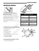
Identification Numbers Identification Numbers PRODUCT IDENTIFICATION M SA XXXXXXXXXXXXXXX MODEL XXXXXXX 0 123456 789012 XXX kW XXX kg PL SERIAL XXXXXXXX NO XXXX min XXX ID Tag E 20xx Briggs & Stratton Power Product Group, LLC XXXXXXXXXXXXXXXXXX XXXXXXXXXXXXXXXXXX Assembled in U.S.A When contacting your authorized dealer for replacement parts, service, or information you MUST have these numbers.
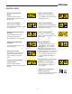
Safety Decals All DANGER, WARNING, CAUTION and instructional messages on your unit should be carefully read and obeyed. Personal bodily injury can result when these instructions are not followed. The information is for your safety and it is important! The safety decals below are on your unit. SAFETY DECALS This unit has been designed and manufactured to provide you with the safety and reliability you would expect from an industry leader in outdoor power equipment manufacturing.
Safety Icons SAFETY ICONS Danger: Machine Rollover. Warning: Read Operator’s Manual. Operating on steep slopes can cause sliding and loss of steering, control and rollover. Read and understand the Operator’s Manual before using this machine. Danger: Thrown Objects. Danger: Dismemberment. This machine is capable of throwing objects and debris. Keep bystanders away. This machine can amputate limbs. Keep bystanders and children away when engine is running. Warning: Remove Key Before Servicing.
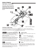
Features & Controls FEATURES & CONTROLS N ep o ro t fo du r ct io n Please take a moment and familiarize yourself with the name, location, and function of these controls so that you will better understand the safety and operating instructions provided in this manual. Figure 1B. Control Locations CONTROL FUNCTIONS The information below briefly describes the function of individual controls. Starting, stopping, driving, and mowing require the combined use of several controls applied in specific sequences.
Features & Controls PTO (Power Take Off) Switch Fuel Tank Cap The PTO Switch engages and disengages the mower blades. To remove cap, turn counterclockwise. To engage the mower blades, pull up on the switch. To disengage the mower blades, push down on the switch. 16 HP Models When the PTO engagement lever or switch is in the Engaged position, the Engine Kill system is activated. Parking Brake DISENGAGE Releases the parking brake. ENGAGE Locks the parking brake.
SAFETY INTERLOCK SYSTEM OPERATION (S/N: 2013136021 & ABOVE) Before first time operation: • Be sure to read all information in the Safety and Operation sections before attempting to operate this tractor and mower. • Become familiar with all of the controls and how to stop the unit. • Drive in an open area without mowing to become accustomed to the unit. GENERAL OPERATING SAFETY This unit is equipped with safety interlock switches and other safety devices.
Operation DRIVING THE MOWER WARNING • • • • Make sure the PTO switch is disengaged. Start the engine (see STARTING THE ENGINE). Set the throttle control to FULL. Manual Start: Grasp the operator presence / parking brake handles and the handle bar grips at the same time to deactivate engine kill system and disengage the parking brake. • Electric Start: Push down on both of the engine kill / operator presence handles to deactivate the engine kill system.
Operation PUSHING THE MOWER BY HAND STOPPING THE MOWER • Returning the ground speed control levers to the neutral position will stop movement. • Disengage the PTO. • Manual Start Release the operator presence / parking brake handles to engage the parking brake. • Electric Start: Engage the parking brake. • Move the throttle control to mid-throttle position and turn the ignition key to OFF. Remove the key. DO NOT TOW MOWER Towing the unit will cause hydraulic transmission damage.
Operation STORAGE WARNING Temporary Storage (30 Days Or Less) Never store the unit, with gasoline in engine or fuel tank, in a heated shelter or in enclosed, poorly ventilated enclosures. Gasoline fumes may reach an open flame, spark or pilot light (such as a furnace, water heater, clothes dryer, etc.) and cause an explosion. Remember, the fuel tank will still contain some gasoline, so never store the unit indoors or in any other area where fuel vapor could travel to any ignition source.
Operation CUTTING HEIGHT ADJUSTMENT The cutting height can be adjusted within two different ranges. The High Range covers 4-1/2” - 2-1/2” (11,4 - 6,4cm) and the Low Range covers 3-1/2” - 1-1/2” (8,9 3,8cm). See Figure 3 for deck height indicator. Before adjusting the cutting height, you must first determine the average cutting height. Depending on the range you plan to use, it may be necessary to adjust the deck lift pivot locations and the pulley spacer positions.
Operation GROUND SPEED CONTROL LEVER LOCATION ADJUSTMENT Manual Start A The control levers can be adjusted in two ways to provide a comfortable working range when operating the machine at the average mowing speed. Adjust both the lever height and lever position at the same time to obtain the most comfortable working position B D Adjusting the Lever Height: 1. Loosen the lever fastener (B, Figure 5) to adjust the lever height.
N ep o ro t fo du r ct io n R Notes
Ferris Industries - a division of Simplicity Manufacturing Inc. Owner's Limited Warranty Information (Effective 04/28/2004) Thank you for purchasing Ferris commercial mowing equipment. Please take a few minutes to read this limited warranty information. It contains all the information you will need to have your Ferris mower repaired in the unlikely event that a breakdown covered by this limited warranty should occur.
N ep o ro t fo du r ct io n The Ferris logo is a trademark of Briggs & Stratton Corporation Milwaukee, WI, USA. R The Simplicity logo is a trademark of Briggs & Stratton Corporation Milwaukee, WI, USA. The Snapper Pro logo is a trademark of Briggs & Stratton Corporation Milwaukee, WI, USA. Briggs & Stratton Power Products Group, LLC. Copyright © 2010 Briggs & Stratton Corporation Milwaukee, WI, USA. All Rights Reserved. Ferris Industries 5375 North Main Street Munnsville, NY 13409 800-933-6175 www.