ATTACHMENT OPERATOR’S MANUAL 42” Single-Stage Snowthrower 42” Snowthrower Attachment Mfg. No. 1694920 Description 42” Single-Stage Snowthrower 1733943 Revision 01 Rev.
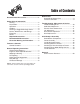
Table of Contents Maintenance Schedule for Normal Care ...............................9 General Lubrication .........................................9 Recommended Accessories ..............................1 Safety Rules & Information Training ............................................................2 Preparation ......................................................2 Operation.........................................................2 Children ...........................................................
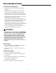
Safety Rules & Information This machine is capable to amputating hands and feet and throwing objects. Read these safety rules and follow them closely. Failure to obey these rules could result in loss of control of unit, severe personal injury or death to you, or bystanders, or damage to property or equipment. The triangle in text signifies important cautions or warnings which must be followed. TRAINING OPERATION 1.
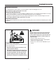
Safety Decals 7. Always observe safe refueling and fuel handling practices when refueling the unit after transportation or storage. 8. Always follow the engine manual instructions for storage preparations before storing the unit for both short and long term periods. 9. Always follow the engine manual instructions for proper start-up procedures when returning the unit to service. 10. Maintain or replace safety and instruction labels as necessary. 11.
Safety Decals SAFETY DECALS All DANGER, WARNING, CAUTION and instructional messages on your unit should be carefully read and obeyed. Personal bodily injury can result when these instructions are not followed. The information is for your safety and it is important! The safety decals below are on your unit. This unit has been designed and manufactured to provide you with the safety and reliability you would expect from an industry leader in outdoor power equipment manufacturing.
Required Accessories Required Accessories It is required that tire chains and two rear wheel weights or Quick Tach Weights are used. Never operate on slopes greater than 17.6% (10°). Recommended Accessories A rear-mounted weight box can also be added for additional traction. The maximum weight added to the tractor should not exceed 35 lbs. per wheel, plus 100 additional pounds in the rear weight box. For operation on slopes greater than 15% (8.
Features & Controls D CONTROL FUNCTIONS The information below briefly describes the function of individual controls. Operating the tractor and attachment requires the combined use of these controls and additional controls whose operation is described in the tractor Operator’s Manual. B A Please take a moment and familiarize yourself with the name, location, and function of these controls so that you will better understand the safety and operating instructions provided in this manual. E E Figure 1.
General Operating Instructions WARNING WARNING Perform the Safety System Interlock test found in your tractor Operator’s Manual. If tractor does not pass the test, do not operate the tractor. See your authorized dealer. Under no circumstances should you attempt to defeat the safety system. If auger does not start and stop when engaging/disengaging electric clutch, see your authorized dealer. Under no circumstances should you attempt to defeat the safety system.
General Operating Instructions Snow Removal Suggestions • Determine the best snow removal pattern before beginning. • Wind direction is an important factor to consider. Rotate the spout to discharge snow downwind. • Plan the pattern so that you avoid throwing snow on cleared areas and on yourself as you are operating. • When land contour permits, it is best to travel in the longest direction to minimize turning.
Maintenance WARNING To avoid serious injury, perform maintenance on the unit only when the engine is stopped and all moving parts have stopped. Always remove the ignition key before beginning maintenance or adjustments to prevent accidental starting of the engine. Schedule For Normal Care Care Required Schedule Clean snow and ice from snowthrower. Lubricate snowthrower. After each use. Every 10 hours or at least once a year. General Lubrication Lubricate the snow thrower as shown in Figure 2.
Troubleshooting, Adjustments, & Service TROUBLESHOOTING WARNING While normal care and regular maintenance will extend the life of your equipment, prolonged or constant use may eventually require that service be performed to allow it to continue operating properly. To avoid serious injury, perform maintenance on the tractor or snow thrower only when the engine is stopped and the parking brake engaged.
Troubleshooting, Adjustments, & Service Skid Shoe Adjustment On smooth surfaces such as concrete or asphalt, the scraper bar should scrape the surface. On surfaces such as gravel, the scraper bar should be set high enough so that it will not pick up debris. Loosen Nuts to Adjust 1. Loosen the nuts securing the skid shoes (see Figure 3). 2. Raise or lower the scraper bar to the desired height. Use wood blocks to hold the snow thrower in position. 3.
Troubleshooting, Adjustments, & Service Lift Adjustment In the fully raised position the attachment should be 4”-5” off the ground. LIFT HEIGHT ADJUSTMENT 1. Fully raise the attachment lift. The snow thrower should be approximately 4”-5” off the ground. If not, go to step 2. 2. Lower the snow thrower and adjust the front set collar (A, Figure 5) to achieve the correct lift height. Belt Tension Adjustment Adjust belt tension if the tension lever does not adjust belt tension properly. A 1.
Troubleshooting, Adjustments, & Service Belt Replacement E 1. Move tension release lever to the released position (C, Figure 6). 2. Remove the belt from the snow thrower pulley (D, Figure 7). C B 3. Remove the belt from the machine. 4. Install the new belt as shown in Figure 7. 5. Move the belt tension lever to the locked position (B, Figure 6). A D Figure 7. Belt Routing A. V-Pulley B. Idler Pulley C. Electric Clutch Pulley (V-pulley) D. Snow thrower Pulley (V-pulley) E.
Initial Setup & Assembly 1 4 3 5 6 17 2 6 15 16 7 10 8 9 14 12 11 13 QTY QTY 4 4 Ref Qty 1 1 2 2 3 1 4 1 5 1 6 1 7 1 8 1 9 1 Description UPPER WIRING HARNESS REFLECTORS FINAL WIRING HARNESS CHUTE ROTATION SWITCH HITCH SUPPORT SHAFT HAIR PIN COTTER HITCH ASSEMBLY HITCH LATCH PIN AXLE CLIP Ref Qty 10 2 11 1 12 1 13 1 14 1 15 4 16 1 17 1 18 1 Figure 8.
Initial Setup & Assembly CHUTE ASSEMBLY E 1. Carefully unpack and organize Snow thrower parts. D 2. Remove chute rotator drive cover (B, Figure 9) from the snow thrower assembly by removing hex screw (A) and tilting the gearbox cover to disengage tab on opposite side of box. B 3. Remove chute rotator gear from shaft (C). Note location of notch (D) in chute ring gear. Align the notch in the chute assembly with the guide tab at the base of the discharge outlet. C 4.
Initial Setup & Assembly INSTALL HITCH ONTO TRACTOR 1. Remove mower deck. 2. Place hitch on floor in front of tractor, with the hitch mounting arms towards the rear of the tractor. NOTE: If this is a new installation, cut the plastic ties holding the snow thrower drive belt for shipping, but do not remove the belt. 3. On underside of tractor frame, insert hitch support shaft (A, Figure 11) as shown and secure, with the hair pin cotter pin (B) on inside of frame.
Initial Setup & Assembly 7. Lift the hitch (B) and from the left side of the tractor, slide hitch latch pin (A) through the mounting hole in hitch frame, along the tractor frame support fingers (C) and through the final mounting hole in hitch frame. Secure hitch latch pin (A) with the quick clip (D). NOTE: Keep the handle portion of the hitch latch pin towards the front of the tractor. 8. Hitch installation is now complete. ATTACHING BLOWER TO TRACTOR 1. Position snow thrower assembly in front of tractor.
Initial Setup & Assembly 8. Rotate the belt tension lever upwards into the locked position (B, Figure 15), fully tensioning the snow thrower drive belt. NOTE: Do not connect the mower deck lift arm or cable to the belt tension lever. ATTACHING LIFT ARM ASSEMBLY TO TRACTOR 1. On right side of tractor, remove the four (4) hex bolts and nuts (B, Figure 17) from hitch assembly. D 2. Attach lift arm assembly (A) to the tractor frame using the four hex bolts (B) and nuts. 3.
Initial Setup & Assembly ATTACHING CHUTE MOTOR WIRING HARNESS 1. Wiring Harness is in four (4) parts. a. Switch b. Upper wiring harness with main power connector c. Final wiring harness with a square connector on each end. A 2. Remove plug from tractor control panel at position shown and install the chute rotation switch (A, Figure 19). B 3. Plug female receptacle (B, Figure 19) end of the upper wiring harness onto switch. C 4.
Removal Snow Thrower Removal CAUTION Make sure to shut off the engine and locking the tractor brakes or block the rear wheels before beginning the snow thrower removal process. B 1. Fully raise and support the snow thrower with wooden blocks. 2. Loosen the turn buckle (C, Figure 21) and then remove the lift assist spring, turn buckle and axle clamp. A 3. Lower the snow thrower to the ground. 4. Move the belt tension lever to the RELEASED position (A, Figure 22). Figure 22. Belt Tension Lever A.
Removal 7. Disconnect the final wiring harness (B, Figure 24). 8. Remove both quick clips (E, Figure 25) and snow thrower mounting pins (D). E 9. Move the snow thrower assembly (A, Figure 25) out of the way. D 10. Turn the front wheels fully to the left. Remove the latch pin quick clip (D, Figure 26) and slide the latch pin (A) to the left. B C E CAUTION Make sure to support the front of the hitch assembly as it will be loose when the latch pin has been removed. D A Figure 25.
Removal 11. Slide the hitch assembly (A, Figure 27) forwards until the hitch mounting arms (C) are free of the hitch support shaft (B). 12. Slide the hitch to the right to move it from under the tractor. NOTE: The hitch support shaft (B) may be left in position and will not interfere with the operation of the lawn mower deck. IMPORTANT NOTE Inspect the snow thrower assembly, hitch assembly, snow thrower drive belt and all component parts for signs of wear or damage.
Notes 23
MANUFACTURING, INC. 500 N Spring Street / PO Box 997 Port Washington, WI 53074-0997 PRODUCTS 535 Macon Street McDonough, GA 30253 www.SimplicityMfg.com www.Snapper.com 500 N Spring Street / PO Box 997 Port Washington, WI 53074-0997 500 N Spring Street / PO Box 997 Port Washington, WI 53074-0997 www.MasseyLawn.com AGCOLawn.com © Copyright 2006 Simplicity Manufacturing, Inc. All Rights Reserved. Printed in USA.