Bimpliuitq 0 P E RATO Jn UAL rrne ia Frame Snowthrowers intermediate IVlfg. No. 1695302 1695311 1695410 1695313 1695314 1695411 Frame Snowthrowers Description SM11924E B&S 24 SM11924EX B&S 24 (CE) SM11924RX MS B&S 24 (CE) SNP 1924E B&S 24 SNP 11924EX B&S 24 (CE) SNP 1924RX MS B&S 24 (CE) CAUTION: Readand followall instructions. ManualPartNo. 1734501 Revision 01 Rev.
SAVETHESEiNSTRUCTiONS READTHEMANUAL Theoperator'smanualcontains importantsafetyinformation youneedtobe awareof BEFORE youoperateyourunitas well asDURINGoperation.
Table of Contents Co d) Operator Safety .......................................... Readthe Manual ............................................. Safety Rules and information .................................... Safety Decals................................................ Safety icons ................................................ identification Numbers........................................ 2 2 4 8 10 11 Features & Controls ...................................... Control Locations......................
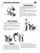
ill g O9 Congratulations on purchasing a superior-quality piece of lawn and garden equipment. Our products are designed and manufactured to meet or exceed all industry standards for safety. Power equipment is only as safe as the operator. If it is misused, or not properly maintained, it can be dangerous! Remember, you are responsible for your safety and that of those around you. Use common sense, and think through what you are doing.
SaletyRulesandInfomatm N0vJng Co This equipment has many moving parts that can injure you or someone else. However, if you are standing in the operator's position, and follow all the rubs in this book, the unit is safe to operate. ,--t- The auger and impeller have spinning parts that can amputate hands and feet. Do not allow anyone near the equipment while it is running! DO NOT clear the discharge chute by hand.
SafetyRules& Informtm This machine is capable to amputating hands and feet and throwing objects. Read these safety rules and follow them closely. Failure to obey these rules could result in loss of control of unit, severe personal injury or death to you, or bystanders, or damage to property or equipment. _The triangle in text signifies important cautions or warnings which must be followed. TRAINING 1.
SafetyRulesaridIflfematm discharge angle. 18. Never direct discharge at bystanders or allow anyone in front of the unit. 19. Never leave a running unit unattended. Always disengage the auger and traction controls, stop engine, and remove keys. 20. Do not operate the unit while under the influence of alcohol or drugs. 21. Keep in mind the operator is responsible for accidents occurring to other people or property. 22.
instructions are not followed. The information is for your safety and it is important. DECALS >, This unit has been designed and manufactured to provide you with the safety and reliability you would expect from an industry leader in outdoor power equipment. O9 The safety decals below are on your unit. If any of these decals are lost or damaged, replace them at once. See your local dealer for replacements.
DGCBIS ALL MODEL DECALS Co ,< Part No. 724172 - SMI/SNAPPER Speed Control Decal, All Models CE MODEL DECALS Part No. 1734591 - SMI/SNAPPER Main Dash Decal, Export - CE Part No. 1727207 Discharge Chute Danger Decal Part No. 1727208 Auger Danger Decal Part No.
SAFETY iCONS WARNING: READ OPERATOR'S MANUAL. Read and understand the Operator's Manual before using this machine. DANGER: THROWN OBJECTS. This machine is capable of throwing objects and debris, Keep bystanders away, WARNING: REMOVE KEY BEFORE SERVICING. Remove the key, disconnect spark plug wire, and consult technical literature before performing repairs or maintenance, 10 WARNING: DISMEMBERMENT. This machine can amputate limbs. Keep bystanders and children away when engine is running.
ProductIdentificationNumbers ""='_ _[_piicity =\_ W_"_ington Manufacturing, inc. WJ 53074-0997 USA North American CE Models CO / ,'-4'< Illllllllllllllllllll_4i_._lllllllllH CE Models Serial Sticker (Only) !!!!!!!!!!!!!!!!!!!!!!! ;x? Model Description Name/Number When contacting your authorized dealer for replacement parts, service, or information you MUST have these numbers.
Festures Please take a moment and familiarize yourseff with the name, location, and function of these controls so that you will better understand the safety and operating instructions provided in this manual. ¢o © ,+_ c © G' L) o5 ¢o dJ I',l (6 d) LL Figure 1. Control CONTROL Locations LOCATIONS The information below briefly describes the function of individual controls. Starting, stopping, and driving require the combined use of several controls applied in specific sequences.
Features& Controls _ Chute Direction Control Rotating the knob to the left will turn the spout to the left side and rotating the knob to the right will rotate the spout to the right side. L_ Chute Deflector Control Chute Deflector Knob: Locks chute deflector in desired position. Tilting the chute deflector UP provides a higher stream and greater distance, while tilting the deflector DOWN provides a lower stream and less distance.
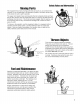
in GENERAL CHECKS OPERATION BEFORE EACH WARNING START-UP 1. Make sure all safety guards are in place and all nuts, bolts and clips are secure. 2. Check to make sure that the clean-out is attached to the auger housing. Do not operate the machine without the clean-out tool properly stored on the auger housing. 3. Check the engine oil level. See your engine owner's manual for procedure and specifications. 4. Check to make sure spark plug wire is attached and spark plug is tightened securely.
Operation O ,'-4- O Figure 2. Engine Controls A. Electric Start Button (Select Models) B. Electric Start Connection (Select Models) C. Stop Switch D. Engine Key E. Starter Handle F. Primer Button G. Choke Knob STARTING CONTROLS 4_ See Figure 2 for the following instructions. Electric Start Electric Start Button - The Electric Start Button (A) activates an electric starter mounted to the engine, eliminating the need to pull the starter handle.
OpepatJon STARTING THE ENGINE 1. Check the oil level. See the Engine Manual How to Check/Add Oil section 2. Make sure equipment drive controls are disengaged. 3. Push the stop switch to the on position (A, Figure 3). Figure 5. Rewind Start A. Starter Cord Handle Figure 3. On/Stop Switch A. On/Stop Switch Selector c © .m ,+_ 4. Insert the engine key (A, Figure 4) into the engine key slot and push fully in to the RUN position. _=. o 5. Turn the choke knob (B) fully clockwise if engine is cold.
Operation STOPPING THE ENGINE , WARNING Gasoline and its vapors are extremely flammable and explosive. Fire or explosion death. can cause severe burns or DO NOT choke the carborator engine. to stop the 1. Move the stop switch (A, Figure 7) to the stop position. 2. Remove the safety key (B). Keep the safety key out of reach of children. 0 -0 © Figure 8. Controls (from operator's A. Speed Selector B. Traction Control C. Auger Engage Control D. Chute Rotator Control Figure 7. Stopping A.
OperaUon DEFLECTOR The distance of the discharged snow is mainly controlled by the position of the deflector. (Engine speed also affects distance of discharge.) The more the deflector is tilted UP, the farther snow will be thrown. 1. Rotate the adjustment knob (C, Figure 9) counterclockwise to loosen then adjust the deflector to the desired position and tighten the deflector adjustment knob by turning it clockwise to secure the deflector in position.
Operation CLEARING A CLOGGED DISCHARGE CHUTE , WARNING Hand contact with the rotating auger/impeller inside the discharge chute is the most common cause of injury associated with snowthrowers. DO NOT use your hand to clean out the discharge chute. To clear the chute: 1. Stop the engine. Remove the key Never store the unit, with gasoline in engine or fuel tank, in a heated shelter or in enclosed, poorly ventilated enclosures.
Beg MAINTENANCE SCHEDULE MAINTENANCE Check / Lubricate Lubricate REQUIRED FREQUENCY Hand Linkage. 10 Hours 10W Oil 10 Hours 10W Oil and Grease snowthrower. Check tire pressure. Change Monthly engine oil.*+ Clean or replace spark plug.+ Check drive linkage/belt Lubricate NOTES tension. Axle Shafts. 20 psi (1.37 bar) 50 Hours; See Engine Manual Yearly See Engine Manual 4-6 Hours See page 24 Yearly Lithium Check auger gear case lubrication.
RegularMaJflteflaflce LUBRICATION IMPORTANT NOTE It is very important that grease fittings on the auger shaft are lubricated regularly. If auger rusts to shaft, damage to worm gear may occur if shear pins do not break. To prevent wheels rusting to axles, it is also necessary to remove the wheels and grease the axles regularly. Remove wheels and grease axles once each year. Apply 5W-30 synthetic motor oil sparingly to the friction disk drive hex shaft (A, Figure 15).
RegWPMaJflteflaflce CHECK / LUBRICATE LINKAGE Check the function of the Hand controls: the controls should function as described in the CONTROLS section. It is critical for the safe operation of the unit that the controls disengage when released, Lubricate as shown in figure 18, IMPORTANT NOTE If the controls do not function properly, lubricate them. If lubrication does not rectify the problem, see your dealer.
CD C_ CD 23
g TROUBLESHOOTING WARNING This section provides troubleshooting and service instructions. Locate the problem and check the possible cause/remedy in the order listed. Also, refer to the engine manufacturer's Manual for additional information. Owner's Before performing any adjustment or service to snowthrower, stop the engine and wait for moving parts to stop. Remove the key. To prevent accidental starting, disconnect the spark plug wire and fasten away from the plug.
Troubleshooting PROBLEM Auger rotates, but snow is not thrown far enough POSSIBLE REMEDY CAUSE 1. Chute deflector too low. 1. Adjust deflector as necessary. 2• Ground speed too fast. 2. Use slower speed selector setting. 3. STOP engine and REMOVE the key. DISCONNECT the spark plug wire. Clear auger using clean-out tool. See warning in SAFETY RULES• 3• Snowthrower clogged• discharge chute 4• Auger belt loose or worn. 4. Check auger drive belt adjustment Poor traction 1. Tires slipping. 1.
AI UStmBfl|$ AUGER DRIVE ADJUSTMENT WARNING , WARNING Do not over-tighten, as this may lift the lever and cause auger drive to be engaged without depressing the Auger Control. , , , With the drive lever released, the hook (B, Figure 20) should barely touch the lever (C) without raising it. There can be a maximum 1/32" clearance as shown. To adjust, loosen nut (D) by holding the adjusting flats (A) and turning nut (D). Turn adjustment flats and hold screw.
Adjustments Run-in Adjustment ALL MODELS 1. After 5 hours of use, check for proper adjustment. Readjust clutch cable if necessary by increasing tension on cable. A small amount of arm movement is permissible if unit passes operating checks described in the Warning above. 8. Note the position of the friction wheel (A, Figure 24). The correct distance from the right side of the friction wheel to the outside of the frame is 4-5/16" (10.95 cm).
Adjustments BELT ADJUSTMENT Auger Drive Belt If your snowthrower will not discharge snow, check the control cable adjustment. If it is correct, then check the condition of the auger drive belt. If it is damaged or loose, replace it (see Belt Replacement in this section of the manual). 1. Disconnect spark plug wire. 2. Remove screw (B, Figure 25) from belt cover (A). Remove belt cover (A). 3. Loosen nut (D, Figure 25) on auger idler pulley (B) and move auger idler pulley towards belt about 1/8 inch (3mm).
SHEAR PIN REPLACEMENT WARNING Do not go near the discharge chute or auger when the engine is running. Do not run the engine with any cover or guard removed. Under most circumstances, if the auger strikes an object which could cause damage to the unit, the shear pin will break. (This protects the gear box and other parts from damage.) The shear pins are located on the auger shaft as shown in Figure 27.
SBrvic6 BELT REPLACEMENT Auger Drive Belt The drive belts are of special construction and must be replaced with original factory replacement belts available from your nearest authorized service center. Some steps require the assistance of a second person. If the auger drive belt is damaged, the snow thrower will not discharge snow. Replace the damaged belt as follows. \ 1. Disconnect the spark plug wire. 2. Loosen the capscrews (A, Figure 28) on each side of the bottom panel (B). 3.
$Brvice . Remove hair pin (A) and slide rod (B) backward about 3 inches (until shaft separates from the worm drive). 11. Lift the Chute and rotator (A, Figure 33) off of the auger housing. Figure 31. Rotator Shaft Removal A. Pin, Hair B. Shaft 10. Remove two 5/16-18 KEPS hex nuts (A, Figure 32), and two 5/16-18 x 1-1/2 carriage bolts (B) securing the offset tube (C) to the tube support bracket (D). Figure 33. Chute and Rotator Removal A. Chute and Rotator 12.
SGrvic6 NOTE: To assemble the auger housing to the frame, have someone hold the auger clutch lever in the ENGAGED position. This will move the idler arm and pulley enough to allow the auger drive pulley to move back into position. 15. Assemble the auger housing (C, Figure 34) to the frame with the four upper taptite screws (A) that were removed in step 12. Tighten the two lower taptite screws (B). Tighten all taptite screws to 40-50 Ib-in (4,5-5,6 Nm). 16.
SBrvic6 o o ®0 Figure 35. Traction Belt Change A. Swing Plate B.
SBrvic6 NOTES qO 0 qO GO u) qO E _o -0 34
NOTE: Specifications are correct at time of printing and are subject to change without notice. * Power Ratings The gross power rating for individual gas engine models is labeled in accordance with SAE (Society of Automotive Engineers) code J1940 (Small Engine Power & Torque Rating Procedure), and rating performance has been obtained and corrected in accordance with SAE J1995 (Revision 2002-05). Torque values are derived at 3060 RPM; horsepower values are derived at 3600 RPM.
C © c_ c_ _m
REPLACEMENT PARTS Replacement parts are available from your authorized dealer. Always use genuine Simplicity / Snapper Service Parts. MAINTENANCE ITEMS Many convenient and helpful service and maintenance items are available from you authorized dealer. Some of these items include: Engine Oil Touch-Up Paint Grease Gun Kit 8 oz. Grease Tube Tire Sealant Degrimer/Degreaser Gas Stabilizer TECHNICAL MANUALS Additional copies of this manual are available, as well as fully illustrated parts lists.
Bimplicilq MANUFACTURING, INC. 500 N Spring Street / PO Box 997 Port Washington, Wl 53074-0997 www.SimplicityMfg.com PRODUCTS 535 Macon Street McDonough, GA 30253 www.Snapper.com Briggs & Stratton Yard Power Products Group Copyright © 2007 Briggs & Stratton Corporation Milwaukee, Wl USA.