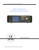
Giga-tronics 2400 and 2500 Series Microwave Signal Generators 2400 and 2500 Series Microwave Signal Generators Programming Manual Programming Manual, Part Number 34783, Rev A, July 2009
Giga-tronics 2400 and 2500 Series Microwave Signal Generators All technical data and specifications in this publication are subject to change without prior notice and do not represent a commitment on the part of Giga-tronics, Incorporated. © 2009 Giga-tronics Incorporated. All rights reserved. Printed in the U.S.A. Warranty Giga-tronics 2400/2500 Series instruments are warranted against defective materials and workmanship for one year from date of shipment.
Giga-tronics 2400 and 2500 Series Microwave Signal Generators Regulatory Compliance Information This product complies with the essential requirements of the following applicable European Directives, and carries the CE mark accordingly. 89/336/EEC and 73/23/EEC EN61010-1 (1993) EN61326-1 (1997) EMC Directive and Low Voltage Directive Electrical Safety EMC – Emissions and Immunity Manufacturer’s Name: Giga-tronics, Incorporated Manufacturer’s Address 4650 Norris Canyon Road San Ramon, California 94583 U.
Giga-tronics 2400 and 2500 Series Microwave Signal Generators Record of changes to this Manual Use the table below to maintain a permanent record of changes to this document. Replacement pages will be issued as a TPCI (Technical Publication Change Instruction), and will be inserted at the front of the binder. Remove the corresponding old pages, insert the new pages, and record the changes here. Do the same thing with TCPI pages that are issued after you have received this manual.
Giga-tronics 2400 and 2500 Series Microwave Signal Generators Table of Contents Table of Contents........................................................................................................................................... i Chapter 1. Safety .................................................................................................................................... 1 1.1 Unsafe Operating Conditions........................................................................................
Giga-tronics 2400 and 2500 Series Microwave Signal Generators 4.7.2 HP 8663 Emulation Commands ........................................................................................132 4.7.3 HP 8673 Emulation Commands ........................................................................................134 4.7.4 HP 8360 Emulation Commands ........................................................................................138 4.7.5 HP 8370 Emulation Commands ..........................................
Giga-tronics 2400 and 2500 Series Microwave Signal Generators Chapter 1. 1. Safety Safety 1.1 Unsafe Operating Conditions If you notice any of the following conditions while operating electronics equipment, IMMEDIATELY de-energize the equipment. • The instrument fails to operate normally, or operates erratically. • The power cable, receptacle, or plug on the instrument is damaged • The instrument causes electrical shock or operates at abnormally high temperature.
1.
Giga-tronics 2400 and 2500 Series Microwave Signal Generators Chapter 2. 2. Introduction Introduction 2.1 Overview Manual Convention: • For simplicity, when generically referring to Giga-tronics Microwave Signal Generators in the 2400 and 2500 Series, the term “2400/2500” may be used. Specific models within either series are referred to when necessary. This manual describes how to program and remotely control the 2400/2500 and 2500B Series Microwave Signal Generators for automated testing.
2. Introduction Giga-tronics 2400 and 2500 Series Microwave Signal Generators 2.
Giga-tronics 2400/2500 Series Microwave Signal Generators Chapter 3. 3. Hardware Interfaces Hardware Interfaces 3.1 Introduction The 2400/2500 has four connectors to choose from for connecting to a computer: • GPIB • LAN (Ethernet) • RS-232 • USB Figure 1 below shows the locations of the connectors on the 2400/2500 rear panel. Descriptions of the connectors are given in Table 1 below. NOTE: Your 2400/2500 may look slightly different, depending on series and model. Figure 1.
3. Hardware Interfaces Giga-tronics 2400/2500 Series Microwave Signal Generators 3.2 Configure the 2400/2500 Hardware Interface 3.2.1 Using the Included USB Cable A USB 2.0 Type A Male to Type B Male cable shipped with the 2400/2500, and provides you with the simplest way to connect a computer to the 2400/2500. The cable connects between a USB port on the computer, and the USB port on the 2400/2500. To use this cable, you must first install Automation Xpress and the USB driver on the computer.
Giga-tronics 2400/2500 Series Microwave Signal Generators 3. Hardware Interfaces 3.2.4 Configure the 2400/2500 Ethernet Connection The following procedure explains how to set the DHCP, IP Address, and Subnet Mask of the 2400/2500 when using the Ethernet (LAN) connector on the rear of the 2400/2500. The instrument is identified via Ethernet connection during remote operations using the IP address set in this procedure. Each unit on the network must have a unique IP address.
3.
Giga-tronics 2400/2500 Microwave Synthesizer Series Chapter 4. 4. Programming Interfaces Programming Interfaces 4.1 Introduction This chapter describes the different programming interfaces and methods for remotely controlling a 2400/2500. 4.2 Select the Remote Programming Language The 2400/2500 can communicate using a variety of languages. Every 2400/2500 is capable of communications using the SCPI (Standard Commands for Programmable Instruments) language or any Giga-tronics native command set.
4. Programming Interfaces Giga-tronics 2400/2500 Microwave Synthesizer Series 4.3 Dynamic Link Library (DLL) A DLL is a collection of routines that can be used by applications or other DLLs. A DLL is provided on the CD-ROM that is included with the 2400/2500 Microwave Signal Generator. When you install Automation Xpress from the CD-ROM onto your computer, the DLL is loaded onto your computer. The routines in the DLL can be used in Visual C++, Visual Basic, and other applications. 4.3.
Giga-tronics 2400/2500 Microwave Synthesizer Series 4. Programming Interfaces 4.3.2 Programming Examples Using the DLL 4.3.2.1 CW Operation Using Visual C++ NOTE: Only bold faced code lines are unique to a specific operation mode. All other lines are supporting lines shared by both CW and List modes. Step Description 1. Perform steps 1 through 5 in Table 6 on page 10 to add the DLL to a Visual C++ project. 2. Write the following code: #include "GT2400.h" #include "stdio.
4. Programming Interfaces Giga-tronics 2400/2500 Microwave Synthesizer Series 4.3.2.2 Programming Example; CW Operation Using Visual Basic Step Description 1. Perform steps 1 through 3 of Table 7 on page 10 to create a Visual Basic project. 2. Write the following ‘This routine sets CW frequency and power of a 2400/2500 synthesizer ‘through GPIB at address 6.
Giga-tronics 2400/2500 Microwave Synthesizer Series 4. Programming Interfaces 4.3.2.3 Programming Example; List Operation Using Visual C++ Step Description 1. Perform steps 1 through 5 of Table 6 to create a Visual C++ project. 2. Write the following code: #include #include #include "gt2400.h" #define SUCCESS 0 //This routine can load any list file to 2400/2500 synthesizer //and set up repeat type and trigger type at user choice.
4. Programming Interfaces Giga-tronics 2400/2500 Microwave Synthesizer Series Step Description 3. Build the project. 4. Run the program. 5. Send trigger.
Giga-tronics 2400/2500 Microwave Synthesizer Series 4. Programming Interfaces 4.3.2.4 Programming Example; Generate Two Frequencies The following example shows how to write code for generating two CW frequencies, separated by a 40 second delay. Step 1. Description //This example sets two CW frequencies in sequence, separated by a 40 second delay. #include "GT2400.h" #include "stdio.h" #include "winbase.h" void main(void) { long STATUS; unsigned long instrumentHandle; printf("f= 23.
4. Programming Interfaces Giga-tronics 2400/2500 Microwave Synthesizer Series 4.3.2.5 Programming Example: List Operation Using Visual Basic Step Description 1. Perform step 1 through step 3 of Table 7 on page 10 to create a Visual Basic project. 2. Write following: ‘This routine can load any list file to 2400/2500 synthesizer ‘and set up repeat type and trigger type.
Giga-tronics 2400/2500 Microwave Synthesizer Series 4. Programming Interfaces 4.3.3 DLL Functions This section describes the DLL functions in detail.
4. Programming Interfaces Giga-tronics 2400/2500 Microwave Synthesizer Series 4.3.3.1 DLL Function; GT2400_FindInstruments GT2400_FindInstruments Purpose Find the addresses of instruments, either through GPIB or RS232, connected to PC. Syntax STATUS GT2400_FindInstruments( Parameter const short connectionType, short addresses[], short *pCount) Description connectionType Input: Connection type.
Giga-tronics 2400/2500 Microwave Synthesizer Series 4. Programming Interfaces 4.3.3.2 DLL Function; GT2400_OpenConnection GT2400_OpenConnection Purpose Establish the communication between the PC and the 2400/2500 with the specified connection interface and address. For an Ethernet connection, call GT2400_SetIPAddress function first to establish the TCP/IP address of the instrument.
4. Programming Interfaces Giga-tronics 2400/2500 Microwave Synthesizer Series 4.3.3.3 DLL Function; GT2400_CloseGPIBConnection GT2400_CloseGPIBConnection Purpose Close one specific GPIB connection. Syntax STATUS GT2400_CloseGPIBConnection( Parameter const unsigned long instrumentHandle) Description instrumentHandle Input: The unique identification of the connected instrument.
Giga-tronics 2400/2500 Microwave Synthesizer Series 4. Programming Interfaces 4.3.3.4 DLL Function; GT2400_CloseAllConnections GT2400_CloseAllConnections Purpose Close all connection. You should always call this function before you close your application to avoid memory leak.
4. Programming Interfaces Giga-tronics 2400/2500 Microwave Synthesizer Series 4.3.3.5 DLL Function; GT2400_SetGPIBAddress GT2400_SetGPIBAddress Purpose Set the GPIB address. Syntax STATUS GT2400_SetGPIBAddress( const unsigned long instrumentHandle, const short address, unsigned long *updatedInstrumentHandle) Parameter Description instrumentHandle Input: The unique identification of the instrument. address Input: GPIB address.
Giga-tronics 2400/2500 Microwave Synthesizer Series 4. Programming Interfaces 4.3.3.6 DLL Function; GT2400_SetServerIPAddr (for Rev 3.0 and above) GT2400_SetServerIPAddr (for Rev 3.0 and above) Purpose Set the TCP/IP address of remote SERVER PC. (example: 194.177.0.
4. Programming Interfaces Giga-tronics 2400/2500 Microwave Synthesizer Series 4.3.3.7 DLL Function; GT2400_GetIPAddress (supported from Revision 3.3) GT2400_GetIPAddress (supported from Revision 3.3) Purpose Get the TCP/IP address of the instrument. (example: 194.177.0.482).
Giga-tronics 2400/2500 Microwave Synthesizer Series 4. Programming Interfaces 4.3.3.8 DLL Function; GT2400_SetIPAddress (supported from Revision 3.3) GT2400_SetIPAddress (supported from Revision 3.3) Purpose Set the TCP/IP address for the instrument. (example: 194.177.0.482) For establishing Ethernet connection with the instrument, this function needs to be called prior to calling GT2400_OpenConnection function.
4. Programming Interfaces Giga-tronics 2400/2500 Microwave Synthesizer Series 4.3.3.9 DLL Function; GT2400_ResetInstrument GT2400_ResetInstrument Purpose Reset the instrument to factory defaults.
Giga-tronics 2400/2500 Microwave Synthesizer Series 4.3.3.10 4.
4. Programming Interfaces 4.3.3.11 Giga-tronics 2400/2500 Microwave Synthesizer Series DLL Function; GT2400_SetRF GT2400_SetRF Purpose Set the RF on or off.
Giga-tronics 2400/2500 Microwave Synthesizer Series 4.3.3.12 4. Programming Interfaces DLL Function; GT2400_GetAttenuation GT2400_GetAttenuation Purpose Get the attenuation value. Syntax STATUS GT2400_GetAttenuation( Parameter const unsigned long instrumentHandle, short *pAttenuation) Description instrumentHandle Input: The unique identification of the instrument. pAttenuation Output: current attenuation in the instrument.
4. Programming Interfaces 4.3.3.13 Giga-tronics 2400/2500 Microwave Synthesizer Series DLL Function; GT2400_SetAttenuation GT2400_SetAttenuation Purpose Set the attenuation of the output power of the 2400/2500. Syntax STATUS GT2400_SetAttenuation( Parameter const unsigned long instrumentHandle, const short attenuation) Description instrumentHandle Input: The unique identification of the instrument attenuation 30 Input: attenuation value, e.g.
Giga-tronics 2400/2500 Microwave Synthesizer Series 4.3.3.14 4. Programming Interfaces DLL Function; GT2400_GetALCLeveling GT2400_GetALCLeveling Purpose Get the current ALC leveling source of the instrument.
4. Programming Interfaces 4.3.3.15 Giga-tronics 2400/2500 Microwave Synthesizer Series DLL Function; GT2400_SetALCLeveling GT2400_SetALCLeveling Purpose Set the ALC leveling source to the instrument.
Giga-tronics 2400/2500 Microwave Synthesizer Series 4.3.3.16 4. Programming Interfaces DLL Function; GT2400_GetErrorMessage GT2400_GetErrorMessage Purpose Convert STATUS code to the corresponding description.
4. Programming Interfaces 4.3.3.17 Giga-tronics 2400/2500 Microwave Synthesizer Series DLL Function; GT2400_GetDLLVersion GT2400_GetDLLVersion Purpose Return the DLL version.
Giga-tronics 2400/2500 Microwave Synthesizer Series 4.3.3.18 4. Programming Interfaces DLL Function; GT2400_GetCW GT2400_GetCW Purpose Read the current CW setting (data) from the instrument.
4. Programming Interfaces 4.3.3.19 Giga-tronics 2400/2500 Microwave Synthesizer Series DLL Function; GT2400_GetCWDataLimit GT2400_GetCWDataLimit Purpose Get the CW data limits of the instrument.
Giga-tronics 2400/2500 Microwave Synthesizer Series 4.3.3.20 4. Programming Interfaces DLL Function; GT2400_SetCW GT2400_SetCW Purpose Set CW.
4. Programming Interfaces 4.3.3.21 Giga-tronics 2400/2500 Microwave Synthesizer Series DLL Function; GT2400_GetPowerOffset GT2400_GetPowerOffset Purpose Get the current power offset value of the instrument.
Giga-tronics 2400/2500 Microwave Synthesizer Series 4.3.3.22 4. Programming Interfaces DLL Function; GT2400_SetPowerOffset GT2400_SetPowerOffset Purpose Set the power offset value to the instrument.
4. Programming Interfaces 4.3.3.23 Giga-tronics 2400/2500 Microwave Synthesizer Series DLL Function; GT2400_GetPowerSlope GT2400_GetPowerSlope Purpose Get the current power slope value of the instrument.
Giga-tronics 2400/2500 Microwave Synthesizer Series 4.3.3.24 4. Programming Interfaces DLL Function; GT2400_SetPowerSlope GT2400_SetPowerSlope Purpose Set the power slope value to the instrument.
4. Programming Interfaces 4.3.3.25 Giga-tronics 2400/2500 Microwave Synthesizer Series DLL Function; GT2400_DownloadList GT2400_DownloadList Purpose Download a list to the GT2400 synthesizer. The file can be prepared beforehand by either MS Excel, or any text editor or AutomationXpress GUI or AutomationXpress DLL list editing functions.
Giga-tronics 2400/2500 Microwave Synthesizer Series 4.3.3.26 4. Programming Interfaces DLL Function; GT2400_GetRepeatType GT2400_GetRepeatType Purpose Get the repeat type of the list to be triggered.
4. Programming Interfaces 4.3.3.27 Giga-tronics 2400/2500 Microwave Synthesizer Series DLL Function; GT2400_SetRepeatType GT2400_SetRepeatType Purpose Set the repeat type of the list to be triggered.
Giga-tronics 2400/2500 Microwave Synthesizer Series 4.3.3.28 4. Programming Interfaces DLL Function; GT2400_GetTriggerType GT2400_GetTriggerType Purpose Get the trigger type to trigger the list.
4. Programming Interfaces 4.3.3.29 Giga-tronics 2400/2500 Microwave Synthesizer Series DLL Function; GT2400_SetTriggerType GT2400_SetTriggerType Purpose Set the trigger type to trigger the list.
Giga-tronics 2400/2500 Microwave Synthesizer Series 4.3.3.30 4. Programming Interfaces DLL Function; GT2400_SetListScanDirection GT2400_SetListScanDirection Purpose Set the list scan direction. Syntax STATUS GT2400_SetListScanDirection( Parameter const unsigned long instrumentHandle, const short direction) Description instrumentHandle Input: The unique identification of the instrument. direction Input: 0 = scan from first point to last point; 1 = scan from last to first.
4. Programming Interfaces 4.3.3.31 Giga-tronics 2400/2500 Microwave Synthesizer Series DLL Function; GT2400_SoftwareTrigger GT2400_SoftwareTrigger Purpose Use the software to trigger the current list.
Giga-tronics 2400/2500 Microwave Synthesizer Series 4.3.3.32 4. Programming Interfaces DLL Function; GT2400_GroupExecutionTrigger GT2400_GroupExecutionTrigger Purpose Send a Group Execution Trigger (G.E.T. is defined in IEEE 488) to all the instruments connected to PC via GPIB.
4. Programming Interfaces 4.3.3.33 Giga-tronics 2400/2500 Microwave Synthesizer Series DLL Function; GT2400_GetListDataLimit GT2400_GetListDataLimit Purpose Get the list data limits of the instrument.
Giga-tronics 2400/2500 Microwave Synthesizer Series 4.3.3.34 4. Programming Interfaces DLL Function; GT2400_LoadListFromFile GT2400_LoadListFromFile Purpose Load a list from a disk file to PC RAM. Syntax STATUS GT2400_LoadListFromFile( Parameter const char filename[], char errText[]) Description filename Input: Name of the file being loaded. errText Output: If there is an error detected by STATUS, errText will hold the description of the problems.
4. Programming Interfaces 4.3.3.35 Giga-tronics 2400/2500 Microwave Synthesizer Series DLL Function; GT2400_CreateNewList GT2400_CreateNewList Purpose Create a new list in PC RAM.
Giga-tronics 2400/2500 Microwave Synthesizer Series 4.3.3.36 4. Programming Interfaces DLL Function; GT2400_SaveListToFile GT2400_SaveListToFile Purpose Save a currently active list from RAM to a disk file. Syntax STATUS SaveListToFile ( Parameter const char filename[], char errText[]) Description filename Input: File name of list to be saved in. errText Output: If there is an error detected by STATUS, errText will hold the description of the problems.
4. Programming Interfaces 4.3.3.37 Giga-tronics 2400/2500 Microwave Synthesizer Series DLL Function; GT2400_ActivateAList GT2400_ActivateAList Purpose Activate the selected list so that the list is ready to respond to a trigger.
Giga-tronics 2400/2500 Microwave Synthesizer Series 4.3.3.38 4. Programming Interfaces DLL Function; GT2400_GetListData GT2400_GetListData Purpose Get the contents of the selected list from DLL allocated RAM into user application.
4. Programming Interfaces 4.3.3.39 Giga-tronics 2400/2500 Microwave Synthesizer Series DLL Function; GT2400_GetListDataWithCorrection GT2400_GetListDataWithCorrection Purpose Get the contents of the selected list from DLL allocated RAM into user application.
Giga-tronics 2400/2500 Microwave Synthesizer Series 4.3.3.40 4. Programming Interfaces DLL Function; GT2400_SetCorrection GT2400_SetCorrection Purpose Edit the correction of the selected list.
4. Programming Interfaces 4.3.3.41 Giga-tronics 2400/2500 Microwave Synthesizer Series DLL Function; GT2400_GetCorrection GT2400_GetCorrection Purpose Get the correction of the selected list.
Giga-tronics 2400/2500 Microwave Synthesizer Series 4.3.3.42 4. Programming Interfaces DLL Function; GT2400_EditApplyCorrection GT2400_EditApplyCorrection Purpose Set flag if correction should apply.
4. Programming Interfaces 4.3.3.43 Giga-tronics 2400/2500 Microwave Synthesizer Series DLL Function; GT2400_EditAListPoint GT2400_EditAListPoint Purpose Edit a selected point in a list. Syntax STATUS GT2400_EditAListPoint( const short position const short insertType, const char listPath[], const unsigned char syncOutEnable, const double frequency, const double power) Parameter Description position Input: position in the list being edited.
Giga-tronics 2400/2500 Microwave Synthesizer Series 4.3.3.44 4. Programming Interfaces DLL Function; GT2400_EditListPoints GT2400_EditListPoints Purpose Edit multiple selected list points in a list with one function call.
4. Programming Interfaces 4.3.3.45 Giga-tronics 2400/2500 Microwave Synthesizer Series DLL Function; GT2400_EditFreqRangeByStepFreq GT2400_EditFreqRangeByStepFreq Purpose Establish a list or insert a sub-list to an existing list by inputting start frequency, stop frequency, step frequency, and power.
Giga-tronics 2400/2500 Microwave Synthesizer Series 4.3.3.46 4. Programming Interfaces DLL Function; GT2400_EditPowerRangeByStepPower GT2400_EditPowerRangeByStepPower Purpose Establish a list or insert a sub-list to an existing list by inputting start power, stop power, step power, and frequency.
4. Programming Interfaces 4.3.3.47 Giga-tronics 2400/2500 Microwave Synthesizer Series DLL Function; GT2400_EditFreqRangeByNumOfPts GT2400_EditFreqRangeByNumOfPts Purpose Establish a long list or insert a sub-list to an existing list by inputting start frequency, stop frequency, power, and number of list points.
Giga-tronics 2400/2500 Microwave Synthesizer Series 4.3.3.48 4. Programming Interfaces DLL Function; GT2400_EditPowerRangeByNumOfPts GT2400_EditPowerRangeByNumOfPts Purpose Establish a long list or insert a sub-list to an existing list by inputting start power, stop power, frequency, and number of list points.
4. Programming Interfaces 4.3.3.49 Giga-tronics 2400/2500 Microwave Synthesizer Series DLL Function; GT2400_EditListSyncOutOption GT2400_EditListSyncOutOption Purpose Edit the sync out option for the current list.
Giga-tronics 2400/2500 Microwave Synthesizer Series 4.3.3.50 4. Programming Interfaces DLL Function; GT2400_EditRFOffTime GT2400_EditRFOffTime Purpose Set the RF off time of a current list in PC RAM. Syntax STATUS GT2400_EditRFOffTime( Parameter RFOffTime const double RFOffTime) Description Input: RF off time for all list points (in ms) 0.
4. Programming Interfaces 4.3.3.51 Giga-tronics 2400/2500 Microwave Synthesizer Series DLL Function; GT2400_EditStepTime GT2400_EditStepTime Purpose Set the step time of a current list in PC RAM. Syntax STATUS GT2400_EditStepTime( Parameter stepTime 68 const double stepTime) Description Input: Step time of the active list (in ms) 0.
Giga-tronics 2400/2500 Microwave Synthesizer Series 4.3.3.52 4. Programming Interfaces DLL Function; GT2400_EditSyncOutDelay GT2400_EditSyncOutDelay Purpose Set the delay time for the sync out pulse generated. Syntax STATUS GT2400_EditSyncOutDelay( Parameter syncOutDelay const double syncOutDelay) Description Input: Delay time of sync out pulse (in ms) 0.
4. Programming Interfaces 4.3.3.53 Giga-tronics 2400/2500 Microwave Synthesizer Series DLL Function; GT2400_CloseAllLists GT2400_CloseAllLists Purpose Remove all existing lists from PC RAM.
Giga-tronics 2400/2500 Microwave Synthesizer Series 4.3.3.54 4. Programming Interfaces DLL Function; GT2400_CloseAList GT2400_CloseAList Purpose Remove the selected list from PC RAM.
4. Programming Interfaces 4.3.3.55 Giga-tronics 2400/2500 Microwave Synthesizer Series DLL Function; GT2400_DeleteAllListPoints GT2400_DeleteAllListPoints Purpose Delete all points of a selected list. The contents of the memory are cleared but the memory is still reserved for this list until the list is closed.
Giga-tronics 2400/2500 Microwave Synthesizer Series 4.3.3.56 4. Programming Interfaces DLL Function; GT2400_DeleteAListPoint GT2400_DeleteAListPoint Purpose Delete a point of a selected list from PC RAM.
4. Programming Interfaces 4.3.3.57 Giga-tronics 2400/2500 Microwave Synthesizer Series DLL Function; GT2400_SetAMState GT2400_SetAMState Purpose Set AM on/off.
Giga-tronics 2400/2500 Microwave Synthesizer Series 4.3.3.58 4. Programming Interfaces DLL Function; GT2400_SetAMSource GT2400_SetAMSource Purpose Set AM source to external/internal.
4. Programming Interfaces 4.3.3.59 Giga-tronics 2400/2500 Microwave Synthesizer Series DLL Function; GT2400_SetAMExtSensitivity GT2400_SetAMExtSensitivity Purpose Set AM sensitivity when AM source is external. Syntax STATUS GT2400_SetAMExtSensitivity( Parameter const unsigned long instrumentHandle, double AMExtSensitivity) Description instrumentHandle Input: The unique identification of the instrument AMExtSensitivity Input: AM sensitivity 0.0 < AMExtSensitivity < 95.
Giga-tronics 2400/2500 Microwave Synthesizer Series 4.3.3.60 4. Programming Interfaces DLL Function; GT2400_SetAMIntWavefrm GT2400_SetAMIntWavefrm Purpose Set the AM internal waveform.
4. Programming Interfaces 4.3.3.61 Giga-tronics 2400/2500 Microwave Synthesizer Series DLL Function; GT2400_SetAMIntRate GT2400_SetAMIntRate Purpose Set the AM internal rate. Syntax STATUS GT2400_SetAMIntRate( Parameter const unsigned long instrumentHandle, const double AMIntRate) Description instrumentHandle Input: The unique identification of the instrument AMIntRate Input: AM internal rate (in Hz) 0.
Giga-tronics 2400/2500 Microwave Synthesizer Series 4.3.3.62 4. Programming Interfaces DLL Function; GT2400_SetAMIntDepth GT2400_SetAMIntDepth Purpose Set the AM internal depth. Syntax STATUS GT2400_SetAMIntDepth( Parameter const unsigned long instrumentHandle, const double AMIntDepth) Description instrumentHandle Input: The unique identification of the instrument AMIntDepth Input: AM internal depth 0.0 <= AMIntDepth <= 95.
4. Programming Interfaces 4.3.3.63 Giga-tronics 2400/2500 Microwave Synthesizer Series DLL Function; GT2400_SetFMState GT2400_SetFMState Purpose Set the FM on/off.
Giga-tronics 2400/2500 Microwave Synthesizer Series 4.3.3.64 4. Programming Interfaces DLL Function; GT2400_SetFMSource GT2400_SetFMSource Purpose Set the FM source to external/internal.
4. Programming Interfaces 4.3.3.65 Giga-tronics 2400/2500 Microwave Synthesizer Series DLL Function; GT2400_SetFMExtMode GT2400_SetFMExtMode Purpose Set the FM source to external/internal.
Giga-tronics 2400/2500 Microwave Synthesizer Series 4.3.3.66 4. Programming Interfaces DLL Function; GT2400_SetFMExtSensitivity GT2400_SetFMExtSensitivity Purpose Set the FM external sensitivity.
4. Programming Interfaces 4.3.3.67 Giga-tronics 2400/2500 Microwave Synthesizer Series DLL Function; GT2400_SetFMIntWavefrm GT2400_SetFMIntWavefrm Purpose Set the FM internal waveform.
Giga-tronics 2400/2500 Microwave Synthesizer Series 4.3.3.68 4. Programming Interfaces DLL Function; GT2400_SetFMIntRate GT2400_SetFMIntRate Purpose Set the FM internal rate. Syntax STATUS GT2400_SetFMIntRate( Parameter const unsigned long instrumentHandle, const double FMIntRate) Description instrumentHandle Input: The unique identification of the instrument FMIntRate Input: FM internal rate (in Hz) 0.
4. Programming Interfaces 4.3.3.69 Giga-tronics 2400/2500 Microwave Synthesizer Series DLL Function; GT2400_SetFMIntDev GT2400_SetFMIntDev Purpose Set the FM internal deviation.
Giga-tronics 2400/2500 Microwave Synthesizer Series 4.3.3.70 4. Programming Interfaces DLL Function; GT2400_SetPMState GT2400_SetPMState Purpose Set the PM on/off.
4. Programming Interfaces 4.3.3.71 Giga-tronics 2400/2500 Microwave Synthesizer Series DLL Function; GT2400_SetPMSource GT2400_SetPMSource Purpose Set the PM state to internal or external.
Giga-tronics 2400/2500 Microwave Synthesizer Series 4.3.3.72 4. Programming Interfaces DLL Function; GT2400_SetPMExtPolarity GT2400_SetPMExtPolarity Purpose Set the PM state to internal or external.
4. Programming Interfaces 4.3.3.73 Giga-tronics 2400/2500 Microwave Synthesizer Series DLL Function; GT2400_SetPMMode GT2400_SetPMMode Purpose Set the PM internal control mode.
Giga-tronics 2400/2500 Microwave Synthesizer Series 4.3.3.74 4. Programming Interfaces DLL Function; GT2400_SetPMIntTrigPolarity GT2400_SetPMIntTrigPolarity Purpose Set the PM trigger polarity for internal source.
4. Programming Interfaces 4.3.3.75 Giga-tronics 2400/2500 Microwave Synthesizer Series DLL Function; GT2400_SetPMIntWidth GT2400_SetPMIntWidth Purpose Set the PM waveform for internal source. Syntax STATUS GT2400_SetPMIntWidth( Parameter const unsigned long instrumentHandle, const double PMIntWidth) Description instrumentHandle Input: The unique identification of the instrument PMIntWidth Input: PM pulse width (in usec) 0.
Giga-tronics 2400/2500 Microwave Synthesizer Series 4.3.3.76 4. Programming Interfaces DLL Function; GT2400_SetPMIntRFPulseDelay GT2400_SetPMIntRFPulseDelay Purpose Set the PM RF pulse delay for internal source. Syntax STATUS GT2400_SetPMIntRFPulseDelay ( Parameter const unsigned long instrumentHandle, const double PMIntRFPulseDelay); Description instrumentHandle Input: The unique identification of the instrument PMIntRFPulseDelay Input: PM RF pulse delay (in usec) 0.
4. Programming Interfaces 4.3.3.77 Giga-tronics 2400/2500 Microwave Synthesizer Series DLL Function; GT2400_SetPMIntPRI GT2400_SetPMIntPRI Purpose Set the PM trigger PRI (Pulse Repetition Interval) for internal source.
Giga-tronics 2400/2500 Microwave Synthesizer Series 4.3.3.78 4. Programming Interfaces DLL Function; GT2400_SetPMIntSyncDelay GT2400_SetPMIntSyncDelay Purpose Set the PM sync out delay for internal source. Syntax STATUS GT2400_SetPMIntSyncDelay ( Parameter const unsigned long instrumentHandle, const double PMIntSyncDelay); Description instrumentHandle Input: The unique identification of the instrument PMIntSyncDelay Input: PM sync out delay (in usec) 0 usec <= PMIntSyncDelay <= PRI – 0.
4. Programming Interfaces Giga-tronics 2400/2500 Microwave Synthesizer Series 4.4 SCPI Command Set The SCPI format and commands supported by 2400/2500 is explained in this section. 4.4.1 SCPI Command Format SCPI conformance requires adherence to a strict syntax structure. The typographic conventions employed in the tables within each of the subsystem descriptions under “SCPI Command Subsystems”, below, are summarized in this section.
Giga-tronics 2400/2500 Microwave Synthesizer Series 4. Programming Interfaces 4.4.2 SCPI Commands The 2400/2500 SCPI commands are divided into subsystems. The following sections describe the 2400/2500 SCPI commands, and are organized according to subsystems. 4.4.2.1 SCPI Commands; Output Subsystem Table 8 Output Subsystem SCPI Commands Command Syntax Description OUTPut[:STATe] ON|OFF|1|0 Turns the signal at the RF OUT connector on or off. OUTPut[:STATe]? Queries the RF OUTPUT state.
4. Programming Interfaces Table 9 Giga-tronics 2400/2500 Microwave Synthesizer Series Source Subsystem – CW Mode SCPI Commands Command Syntax Description [SOURce]:PHASe:[ADJust:] n (RADians|DEGrees) Sets the relative phase of the output signal. The default units are in radians where the range is -2 pi < n < +2 pi. The command also accepts phase offsets in degrees where the range is -360° < n < +360°. Radians are the default units if no units are specified.
Giga-tronics 2400/2500 Microwave Synthesizer Series 4. Programming Interfaces 4.4.2.3 SCPI Commands; Source Subsystem – Power Table 10 Source Subsystem – Power SCPI Commands Command Syntax Description [SOURce]:POWer:ALC:SOURce INTernal|DIODe|PMETer|DPOSitive Selects the source of the feedback signal for the ALC. The DIODe parameter assumes a negative crystal detector is used. DPOSitive allows for the use of a positive crystal detector.
4. Programming Interfaces Giga-tronics 2400/2500 Microwave Synthesizer Series 4.4.2.5 SCPI Commands; Source Subsystem – List Mode Table 12 Source Subsystem – List Mode SCPI Commands Command Syntax Description [SOURce]:LIST:DIRection UP|DOWN Sets the direction of a list when it is run. If UP is set, the list will run from start to end. If DOWN is set, the list will run from end to start. The default is UP. [SOURce]:LIST:DIRection? Queries the currently set list run direction.
Giga-tronics 2400/2500 Microwave Synthesizer Series Table 12 4. Programming Interfaces Source Subsystem – List Mode SCPI Commands Command Syntax [SOURce]:LIST:REPeat SWEEp|STEP|CONTinuous Description Sets the repeat mode for the current list. The choices are: • SWEEp - Upon triggering, the entire list is executed from the beginning, then execution stops. • STEP - Upon triggering, the current list point is executed, then execution stops. The next trigger executes the next point in the list.
4. Programming Interfaces Table 12 Giga-tronics 2400/2500 Microwave Synthesizer Series Source Subsystem – List Mode SCPI Commands Command Syntax Description [SOURce]:LIST:SYNC Sets sync out option to . The sync out option determines how a pulse is emitted from the SYNC OUT connector during List operation. The choices are: • 0 No pulses are emitted from the SYNC OUT connector during List operation.
Giga-tronics 2400/2500 Microwave Synthesizer Series Table 12 4.
4. Programming Interfaces Giga-tronics 2400/2500 Microwave Synthesizer Series 4.4.2.
Giga-tronics 2400/2500 Microwave Synthesizer Series Table 13 4.
4. Programming Interfaces Giga-tronics 2400/2500 Microwave Synthesizer Series 4.4.2.7 SCPI Commands; System Subsystem Table 14 System Subsystem SCPI Commands Command Syntax Description SYSTem:COMMunicate:GPIB[:SELF]:ADDRess
|MAXimum|MINimum Sets the instrument's GPIB address. The choices are as follows: Any integer between 1 and 30. MAXimum Sets the GPIB address to 30. MINimum Sets the GPIB address to 1.Giga-tronics 2400/2500 Microwave Synthesizer Series Table 14 4. Programming Interfaces System Subsystem SCPI Commands Command Syntax Description SYSTem:PRESet Sets device-specific functions to a known state that is independent of the past-use history of the device. The command does not reset any part of the status reporting system. (Same as the *RST command.) SYSTem:VERSion? Queries the SCPI version to which the instrument applies. The response is in the form YYYY.
4. Programming Interfaces Giga-tronics 2400/2500 Microwave Synthesizer Series 4.4.2.8 SCPI Commands; Trigger Subsystem Table 15 Trigger Subsystem SCPI Commands Command Syntax Description TRIGger[:IMMediate] Initiates an immediate sweep cycle in List mode. If Repeat Type is set to either single step or single sweep, then the sweep returns to IDLE when complete. (Same as a *TRG, that is a single instrument trigger, as opposed to a GroupExecuteTrigger.
Giga-tronics 2400/2500 Microwave Synthesizer Series 4. Programming Interfaces 4.4.2.9 SCPI Commands; Source Subsystem – Ramp Sweep Table 16 Source Subsystem - Ramp Sweep SCPI Commands Command Syntax Description [SOURce]:FREQuency:STARt [HZ | KHZ | MHZ | GHZ] Sets the ramp start frequency to the value specified by . Hertz is assumed as the units if units are not specified. The start frequency must be set less than the stop frequency.
4. Programming Interfaces 4.4.2.10 Giga-tronics 2400/2500 Microwave Synthesizer Series SCPI Commands; Source Subsystem – Modulation All commands in the Source subsystem begin with [SOURce], however, [SOURce] is the default command, and therefore it is optional. Table 17 Source Subsystem – Modulation SCPI Commands Command Syntax Description [SOURce]:AM:DEPTh Sets the internal amplitude modulation depth to a percentage value as specified by .
Giga-tronics 2400/2500 Microwave Synthesizer Series Table 17 4. Programming Interfaces Source Subsystem – Modulation SCPI Commands Command Syntax Description [SOURce]:AM:SCALing? Queries the external amplitude modulation scaling. Return value is a percentage per volt. [SOURce]:AM:SOURce INTernal|EXTernal Sets the amplitude modulation source. The choices are: • INTernal Sets the internal AM generator as the AM source. • EXTernal Selects external AM.
4. Programming Interfaces Table 17 Giga-tronics 2400/2500 Microwave Synthesizer Series Source Subsystem – Modulation SCPI Commands Command Syntax Description [SOURce]:FM:INTernal:FREQuency? Queries the current rate of the internal frequency modulation generator. The return value is in Hertz. [SOURce]:FM:INTernal:FUNCtion:SHAPe OFF|SINE|SQUare|TRIangle|PRaMP Sets the shape of the internal frequency modulation generator waveform.
Giga-tronics 2400/2500 Microwave Synthesizer Series Table 17 4. Programming Interfaces Source Subsystem – Modulation SCPI Commands Command Syntax [SOURce]:FM:STATe ON|OFF|1|0 [SOURce]:FM:STATe? Description Sets the frequency modulation mode on or off. The choices are: • 1|ON Sets FM mode to on. • 0|OFF Sets FM mode to off. Queries the frequency modulation mode. The returned values are: • 1 FM mode is currently on. • 0 FM mode is currently off.
4. Programming Interfaces Table 17 Giga-tronics 2400/2500 Microwave Synthesizer Series Source Subsystem – Modulation SCPI Commands Command Syntax Description [SOURce]:PM:INTernal:FUNCtion:SHAPe ? Queries the shape of the internal phase modulation generator waveform. Returns: "Off", "Sine", "Square", "Triangle", or "Pos Ramp". [SOURce]:PM:SENSitivity Sets the phase modulation external sensitivity to the value specified by . The value is in Hertz per volt.
Giga-tronics 2400/2500 Microwave Synthesizer Series Table 17 4. Programming Interfaces Source Subsystem – Modulation SCPI Commands Command Syntax [SOURce]:PULM:EXTernal:POLarity NORMal|INVerted Description Determines the polarity of the signal at the PULSE IN connector that produces an RF output during pulse modulation. The choices are: • NORMal RF at the RF OUT connector will be on when the signal at the PULSE IN connector is at a TTL high.
4.
Giga-tronics 2400/2500 Microwave Synthesizer Series Table 17 4. Programming Interfaces Source Subsystem – Modulation SCPI Commands Command Syntax [SOURce]:PULSe:MODE OFF | TRIGered | CONTinuous | GATEd Description Sets the internal pulse modulation mode (Not available with Option 17 or 17A). The choices are: • OFF - Turns internal pulse modulation mode off.
4.
Giga-tronics 2400/2500 Microwave Synthesizer Series 4.4.2.11 4.
4. Programming Interfaces Giga-tronics 2400/2500 Microwave Synthesizer Series 4.5 IEEE 488.2 Common Commands Table 20 Command *CLS Name Clear Status IEEE 488.2 Common Commands Description Clears the event registers in all status groups. It also clears the Event Status Register and the Error/Event Queue. *ESE Standard Event Status Enable Sets the Standard Event Status Enable Register. A service request is issued whenever the specified event has occurred. Range of : 0 – 255.
Giga-tronics 2400/2500 Microwave Synthesizer Series Table 20 Command 4. Programming Interfaces IEEE 488.2 Common Commands Name Description *TST? Self-Test Self-Test Query. It returns '0' if the test succeeds, and '1' if the test fails. The test sets a predefined group of CW frequencies and power levels. After each frequency and power is set, the firmware reads the instrument's LOCK/ LEVEL status. If failing the lock/level, the test is failed.
4. Programming Interfaces Giga-tronics 2400/2500 Microwave Synthesizer Series 4.6 GT-12000 Native Commands 4.6.1 GT-12000 Native Commands: CW and System The native commands below are CW and System Commands.
Giga-tronics 2400/2500 Microwave Synthesizer Series 4. Programming Interfaces 4.6.2 GT-12000 Native Commands: List Mode Table 22 Number GT-12000 Native Commands: List Mode Commands Command Name Comments 9 IH Clear all lists 10 L1 Set repeat type to continuous 11 L2 Set repeat type to single sweep 12 L4 Set repeat type to single step 13 LA m, n Add a new point to the end of the existing list. (Note: Parameter n must be the index of the last point starting from 0, i.e.
4. Programming Interfaces Table 22 Number Giga-tronics 2400/2500 Microwave Synthesizer Series GT-12000 Native Commands: List Mode Commands Command Name Comments 27 LGLF d HZ|KZ|KHZ|MZ|MHZ|GZ|GHZ Set list range frequency to d. 28 LGI n Insert frequency range as list n 29 LGIP n d Insert power list range to the end of the existing list. (Note: Parameter n and d are not used, and kept in the command for backward compatibility) 30 LR n Set the existing list waiting on trigger to run.
Giga-tronics 2400/2500 Microwave Synthesizer Series 4. Programming Interfaces 4.6.3 GT-12000 Native Commands: Amplitude Modulation Table 23 Number GT-12000 Native Commands: Amplitude Modulation Command Name Comments 37 AD d Sets the amplitude modulation depth to a percentage value. 38 AM n Activates and selects the source of the Amplitude Modulation according to the following: n = 0 Deactivate Amplitude Modulation. n = 1 Activate external AM n = 2 Activate internal AM and select sine wave.
4. Programming Interfaces Giga-tronics 2400/2500 Microwave Synthesizer Series 4.6.4 GT-12000 Native Commands: Frequency Modulation Table 24 Number Case # GT-12000 Native Commands: Frequency Modulation Command Name Comments Case Name Comments 42 FD d HZ|KZ|KHZ|MZ|MHZ|GZ|GHZ Sets the Frequency Modulation deviation to d. 43 FM n Activates and selects the source of the Frequency Modulation according to the following: n = 0 Deactivate Frequency Modulation. n = 1 Activate external FM.
Giga-tronics 2400/2500 Microwave Synthesizer Series 4. Programming Interfaces 4.6.5 GT-12000 Native Commands: Phase Modulation Table 25 GT-12000 Native Commands: Phase Modulation Number Name Comments 46 PHD d HZ|KZ|KHZ|MZ|MHZ| GZ|GHZ Set trigger mode (n=0 BNC, n=1 GPIB/GET) not yet implemented 47 PHM n Activates and selects the source of the Phase Modulation (ΦM )according to the following: n = 0 Deactivate ΦM. n = 1 Activate external Phase Modulation.
4. Programming Interfaces Giga-tronics 2400/2500 Microwave Synthesizer Series 4.6.6 GT-12000 Native Commands: Pulse Modulation Table 26 Number GT-12000 Native Commands: Pulse Modulation Name Comments 50 PM n Activates and selects the source of the Pulse Modulation according to the following: n = 0 Deactivate Pulse Modulation. n = 1 Activate external positive true PM. n = 2 Activate internal PM. n = 3 Activate external negative true PM.
Giga-tronics 2400/2500 Microwave Synthesizer Series 4. Programming Interfaces 4.7 Emulation 4.7.1 HP 834X Emulation Commands NOTE 1: Not all HP834X commands are implemented. For a complete list of commands see the Operating Manual of a particular instrument. Some commands may have to be customized for your application. Table 27 Number HP 834X Emulation Commands Command Name 1. 2. 3. 4. A1 A2 A3 AL m n 5. 6. 7. 8. 9. 10. 11. 12. 13. 14. 15. 16. 17. 18. 19. 20. 21. 22. 23. 24. 25.
4. Programming Interfaces Table 27 Number Command Name 26. 27. 28. 29. 30. 31. 32. 33. 34. M3 d t M4 d t M5 d t MC MP m NA 1b OA OB OC 35. 36. 37. 38. 39. 40. 41. 42. 43. 44. 45. 46. 47. 48. 49. 50. 51. 52. 53. 54. 55. 56. 57. 58. 59. 60.
Giga-tronics 2400/2500 Microwave Synthesizer Series Table 27 Number 61. 62. 63. 64. 65. 66. 67. 68. 69. 70. 71. 72. 73. 74. 75. 75. 2 HP 834X Emulation Commands Command Name SG SHCF d t SHPL d t SHPS d t SHS1 m SHSL d t SL m d t SP d t SV n T1 T2 T3 TI 1b TL d t TS UP 4.
4. Programming Interfaces Giga-tronics 2400/2500 Microwave Synthesizer Series 4.7.2 HP 8663 Emulation Commands Table 28 Number Command HP 8663 Emulation Commands Description 1. AP Turn RF on 2. AP d (DM|DB|+D|-D) Set RF output amplitude to a specified level and turn RF on 3. AO/A0 Turn RF off 4. AM d (PC) Turn AM on and set AM sensitivity in % 5. CT Set the configure trigger for sweeping 6. DN Decrement active parameter by the step size 7.
Giga-tronics 2400/2500 Microwave Synthesizer Series Table 28 Number Command 4. Programming Interfaces HP 8663 Emulation Commands Description 26. SP n Call special function n 27. ST n Store instrument state to register 1 to 9 28. T1 Set step time to 0.5 ms/sweep 29. T2 Set step time to 1 ms/sweep 30. T3 Set step time to 2 ms/sweep 31. T4 Set step time to 10 ms/sweep 32. T5 Set step time to 100 ms/sweep 33. TR Trigger configure trigger for sweep 34.
4. Programming Interfaces Giga-tronics 2400/2500 Microwave Synthesizer Series 4.7.3 HP 8673 Emulation Commands Table 29 Number HP 8673 Emulation Commands Command Description 1. A0, A1, AO Turn AM Off 2. A2 Set AM to 30% range 3. A3 Set AM to 100% range 4. AP d (DB|DM) Set CW output power level 5. B0 Set filter switching mode to normal 6. B1,BY Set filter switching mode to bypass 7. C1 Set Internal Automatic Leveling Control 8.
Giga-tronics 2400/2500 Microwave Synthesizer Series Table 29 Number 4. Programming Interfaces HP 8673 Emulation Commands Command Description 28. FAOA Read start frequency 29. FB d (GZ|MZ|KZ|HZ) Set sweep stop frequency 30. FBOA Read stop frequency 31. FI d (GZ|MZ|KZ|HZ) Set frequency Increment step 32. FIOA Get frequency increment 33. FN d (GZ|MZ|KZ|HZ) Set frequency increment step 34. FO d (GZ|MZ|KZ|HZ) Set frequency offset 35. FR d (GZ|MZ|KZ|HZ) Set CW frequency 36.
4. Programming Interfaces Giga-tronics 2400/2500 Microwave Synthesizer Series Table 29 Number HP 8673 Emulation Commands Command Description 57. PL d (DB|DM) Set CW output power level 58. PO Pulse off 59. R0 Turn RF off 60. R1 Turn RF on 61. RA d (DB|DM) Set output level range 62. RAOA Read output level range 63. RC0 Instrument Preset 64. RC n Recall Instrument state 65. RD Range down by 10 dB 66. RF0 Turn RF off 67. RF1 Turn RF on 68.
Giga-tronics 2400/2500 Microwave Synthesizer Series Table 29 Number 4. Programming Interfaces HP 8673 Emulation Commands Command Description 84. VEOA Read vernier setting 85. W0 Sweep mode off 86. W1 Sweep mode off 87. W2 Auto sweep mode 88. W3 Manual sweep mode 89. W4 Single sweep arm or execute 90. W5 Single sweep arm only 91. W6 Single sweep arm and execute 92.
4. Programming Interfaces Giga-tronics 2400/2500 Microwave Synthesizer Series 4.7.4 HP 8360 Emulation Commands The HP8360 command set is made up of the standard SCPI commands with the additional commands listed in the table below. In standard SCPI, all queries are terminated with a whereas in HP8360 emulation mode, only a is used. Also, standard SCPI requires an EOI as a terminator for GPIB communication; in HP8360 emulation, a , a , or a is acceptable in place of an EOI.
Giga-tronics 2400/2500 Microwave Synthesizer Series 4. Programming Interfaces 4.7.5 HP 8370 Emulation Commands The HP8370 command set is made up of the standard SCPI commands with the additional commands listed in Table 31 In standard SCPI, all queries are terminated with a whereas in HP8370 emulation mode, only a is used. Also, standard SCPI requires an EOI as a terminator for GPIB communication; in HP8370 emulation, a , a , or a is acceptable in place of an EOI.
4. Programming Interfaces Giga-tronics 2400/2500 Microwave Synthesizer Series 4.7.6 GT900 Emulation Commands Table 32 Giga-tronics GT900 Command Set Command Description DISP o Switch Display on/off FA d Set CW frequency or Sweep start frequency according to the operation mode (in MHz) FB d Set Sweep stop frequency (in MHz) FC d Set Sweep step frequency (in MHz) GEN t Set operation mode.
Giga-tronics 2400/2500 Microwave Synthesizer Series Table 32 Command 4.
4. Programming Interfaces Giga-tronics 2400/2500 Microwave Synthesizer Series 4.7.
Giga-tronics 2400/2500 Microwave Synthesizer Series 4. Programming Interfaces 4.7.8 Systron Donner 16XX Emulation Commands 4.7.8.
4. Programming Interfaces Giga-tronics 2400/2500 Microwave Synthesizer Series 4.7.8.
Giga-tronics 2400/2500 Microwave Synthesizer Series 4. Programming Interfaces 4.7.8.3 Power Level Table 36 Systron Donner 16XX Emulation Command Set — Power Output Power Level Setting Commands Internal Function (- dB W) N Selects 100 dBW digit 0-1 Value of 100 dBW digit M Selects 10 dBW digit 0-9 Value of 10 dBW digit L Selects 1 dBW digit 0-9 Value of 1 dBW digit K Selects 0.1 dBW digit 0-9 Value of 0.1 dBW digit NOTES: 1.
4. Programming Interfaces Giga-tronics 2400/2500 Microwave Synthesizer Series 4.7.8.4 Configuration Versus Output Power Table 37 Systron Donner Configuration Versus Outpur Power Systron Donner 16XX Configuration TYPICAL Maximum Leveled Output Power Standard + 3 dBm Option 01 + 4 dBm Options 01 and 03 + 1 dBm Options 01 and 05 + 1 dBm Option 02 + 5 dBm Options 02 and 03 + 2 dBm Option 03 0 dBm Option 05 0 dBm 4.7.8.
Giga-tronics 2400/2500 Microwave Synthesizer Series 4. Programming Interfaces 4.7.8.6 Vernier Attenuation Commands Table 39 Systron Donner Vernier Attenuation Commands Vernier Attenuation Setting Commands Output Level Relative to MAXIMUM Leveled Power Output N2000 + 10.0 dBr N2010 + 09.0 dBr N2020 + 08.0 dBr N2030 + 07.0 dBr N2040 + 06.0 dBr N2050 + 05.
4. Programming Interfaces Giga-tronics 2400/2500 Microwave Synthesizer Series This page is intentionally blank.
Giga-tronics 2400/2500 Microwave Synthesizer Series Chapter 5. 5. Automation Xpress Automation Xpress 5.1 Introduction Automation Xpress was developed as a way to program the 2400/2500 for automated testing. The Automation Xpress graphical user interface (GUI) is shown in Figure 2 below. 5.1.1 Benefits of Using Automation Xpress Automation Xpress includes an application program interface (API) in the form of a Dynamic Link Library (DLL).
5. Automation Xpress Giga-tronics 2400/2500 Microwave Synthesizer Series 5.2 Install Automation Xpress This section describes how to install and uninstall Automation Xpress on a host computer. Included with the 2400/2500 are the following components for installing and using Automation Xpress. • Automation Xpress software CD • USB Port Adapter software driver • USB 2.
Giga-tronics 2400/2500 Microwave Synthesizer Series Table 41 5. Automation Xpress Install and Uninstall Automation Xpress , Continued Step Action 10. Click Install USB. 11. Follow the instructions on the computer display 12. You must restart your computer for the USB driver to function. You can restart the computer now, or later. NOTE: The computer MUST be restarted before using the USB port and cable with the 2400/2500.
5. Automation Xpress Giga-tronics 2400/2500 Microwave Synthesizer Series 5.3 Start Automation Xpress The easiest way to connect a computer to the 2400/2500 is to use the USB male-to-male cable that is included with the 2400/2500. Automation Xpress must first be installed in the computer to use the cable. Use the following procedure to connect the cable and open Automation Xpress. Table 42 Install the USB Cable and Start Automation Xpress Step Action 1.
Giga-tronics 2400/2500 Microwave Synthesizer Series Table 42 Step 7. 5. Automation Xpress Install the USB Cable and Start Automation Xpress Action The Remote Connection screen appears on the 2400/2500 display (see Figure 4 below). Figure 4. Remote Connection Screen Giga-tronics Remote at USB Connection 8. The CW Mode Dialog Box appears in the AX GUI (see Figure 5 below). Figure 5.
5. Automation Xpress Giga-tronics 2400/2500 Microwave Synthesizer Series 5.4 Automation Xpress GUI Description The main areas of the AX GUI are shown in Figure 6 below. These areas are described in detail on the following pages. NOTE: There is an extensive Help feature in Automation Xpress that helps you quickly learn how to get the most out of Automation Xpress. To open Help in the Automation Xpress GUI: Click on Help > Contents. Figure 6.
Giga-tronics 2400/2500 Microwave Synthesizer Series 5. Automation Xpress 5.4.1 Tool Bar This section describes the Tool Bar area of the AX GUI (see Figure 7). The Tool Bar provides access to the functions and settable parameters of Automation Xpress. Figure 7. AX GUI: Tool Bar and Indicators Tool Bar The Tool Bar has two areas (see Figure 8 below): • The top Menu area; the menus are described on the following pages. • The bottom Function area; the Function buttons are described on page 164. Figure 8.
5. Automation Xpress Giga-tronics 2400/2500 Microwave Synthesizer Series 5.4.1.2 Edit Menu The Edit Menu provides standard text editing tools (see Figure 10). Figure 10. Edit Menu 5.4.1.3 View Menu The View Menu lets you select which windows are viewed in the Automation Xpress GUI (see Figure 11). Figure 11. View Menu 5.4.1.
Giga-tronics 2400/2500 Microwave Synthesizer Series 5. Automation Xpress 5.4.1.4.1 Operation > CW Mode The CW Mode window (see Figure 13) opens by default whenever Automation Xpress is launched. Figure 13. CW Mode Window 5.4.1.4.2 Operation > List Mode > List Controller Open by clicking Operation > List Mode > List Controller. See Figure 14 below. Figure 14.
5. Automation Xpress Giga-tronics 2400/2500 Microwave Synthesizer Series 5.4.1.4.3 Operation > List Mode > List Editor Open by clicking Operation > List Mode > List Editor. See Figure 15 below. Figure 15. List Editor 5.4.1.4.4 Operation > Modulation > See Figure 16 below.
Giga-tronics 2400/2500 Microwave Synthesizer Series 5. Automation Xpress 5.4.1.4.5 Operation > Modulation > Amplitude Modulation The Amplitude Modulation window is shown in Figure 17. Figure 17. Amplitude Modulation Settings Window 5.4.1.4.6 Operation > Modulation > Frequency Modulation The Frequency Modulation window is shown in Figure 18. Figure 18.
5. Automation Xpress Giga-tronics 2400/2500 Microwave Synthesizer Series 5.4.1.4.7 Operation > Modulation > Pulse Modulation The Pulse Modulation window is shown in Figure 19. Figure 19. Pulse Modulation Settings Window 5.4.1.4.8 Operation > Modulation > Scan Modulation The Scan Modulation window is shown in Figure 20. Figure 20.
Giga-tronics 2400/2500 Microwave Synthesizer Series 5. Automation Xpress 5.4.1.4.9 Operation > Advanced The Advanced Settings window is shown in Figure 21. Figure 21. Advanced Settings Window 5.4.1.
5. Automation Xpress Giga-tronics 2400/2500 Microwave Synthesizer Series 5.4.1.5.1 System > Interface The Interface window is shown in Figure 23. Figure 23. Interface Settings Window 5.4.1.5.2 System > General Information The General Information Window has information about the 2400/2500 connected to the computer (see Figure 24). Figure 24.
Giga-tronics 2400/2500 Microwave Synthesizer Series 5. Automation Xpress 5.4.1.6 Tools Menu The Tools Menu (see Figure 25) lets you select the format for Auto Programmer to save test routines. Figure 25. Tools Menu 5.4.1.7 Window Menu The Window Menu (see Figure 26) lets you configure the arrangement of the windows in the Automation Xpress. Figure 26. Window Menu 5.4.1.8 The Help Menu The Help Menu (see Figure 27) lets you select the following: • Contents: Opens the online Help.
5. Automation Xpress Giga-tronics 2400/2500 Microwave Synthesizer Series 5.4.1.9 Function Buttons Table 43 below describes the functions of the buttons in the Tool Bar (see Figure 8 on page 155).
Giga-tronics 2400/2500 Microwave Synthesizer Series 5. Automation Xpress 5.4.2 Indicators and RF Button Figure 28 shows the Indicator bar in Automation Xpress. Table 44 describes the functions of the indicators and button. Figure 28. Automation Xpress GUI Indicators Connected Unlocked Unleveled Table 44 Oven Cold Ext. Ref. Unlocked Unleveled RF On/Off AM • Green — Connected; the computer is connected to a 2400/2500, and Automation Xpress has established a connection to the 2400/2500.
5. Automation Xpress Giga-tronics 2400/2500 Microwave Synthesizer Series Table 44 Name AM FM Pulse 166 Automation Xpress Indicators Function Indicates that the 2400/2500 is in AM mode. • Gray — AM Off • Blue — AM On Indicates that the 2400/2500 is in FM mode. • Gray — FM Off • Blue — FM On Indicates that the 2400/2500 is in pulse modulation (PM) mode.
Giga-tronics 2400/2500 Microwave Synthesizer Series 5. Automation Xpress 5.5 Auto Programmer 5.5.1 Introduction Auto Programmer is a function within Automation Xpress that allows you to remotely program the 2400/2500 using only the buttons and settings within Automation Xpress. Auto Programmer interprets your sequence of actions in Automation Xpress, and converts them into a format usable within a programming application. The general procedure for using Auto Programmer is shown below.
5. Automation Xpress Giga-tronics 2400/2500 Microwave Synthesizer Series 5.5.2 Auto Programmer Examples 5.5.2.1 Generate Code for a C/C++ File This method is to generate the code by exporting to a file. The advantage of this method is simplicity. You only see the file directly related to your actions on GUI. However, you will have to create a project for it in order to compile. This can be achieved easily by looking at the result of second method. Table 46 Generate code to a C/C++ File Step 1.
Giga-tronics 2400/2500 Microwave Synthesizer Series 5. Automation Xpress 5.5.2.3 Generate Code to a Visual Basic File This method generates code by exporting to a file. The advantage of this method is simplicity. You only see the file directly related to your actions in the Automation Xpress GUI. However, you will have to create a project for it in order to compile. This can be achieved easily by looking at the result of second method. Table 48 Step Generate code to a Visual Basic File Action 1.
5. Automation Xpress Giga-tronics 2400/2500 Microwave Synthesizer Series 5.5.2.5 Generate a SCPI command script The following example sets up an arbitrary list for external triggers. Each external single pulse moves the list point one step forward. Table 50 Generate SCPI Command Script Step 1. Description Turn on AutoProgrammer. Note: Opening the AutoProgrammer window (Tools | AutoProgrammer from menu) turns on the AutoProgrammer. Operations on GUI will be recorded from this point on. 2.
Giga-tronics 2400/2500 Microwave Synthesizer Series Chapter 6. 6. Status register System Status Register System 6.1 Introduction The Status Register System holds information about the 2400/2500 during remote operation. Several status registers can be queried for specific information about the state of the instrument or the status of events relating to its operation. These registers can be queried directly or can be configured to initiate a service request whenever an expected condition has occurred.
6. Status register System Giga-tronics 2400/2500 Microwave Synthesizer Series Figure 30.
Giga-tronics 2400/2500 Microwave Synthesizer Series 6. Status register System 6.2 Status Byte and Service Request Enable Registers The Status Byte Register is the primary status register. It is the top-level register used to track changes in the state of the 2400/2500. The summary bits of lower-level status registers are set in the Status Byte Register when certain conditions occur that are being monitored by and have been enabled in those lower-level registers.
6. Status register System Giga-tronics 2400/2500 Microwave Synthesizer Series 6.3 Standard Event Status and Standard Event Status Enable Registers The Standard Event Status Register is one of the lower-level status registers. It monitors certain common instrument status conditions. When a condition occurs that is being monitored by this register, and that condition has been enabled by the Standard Event Status Enable Register, bit 5 is set in the Status Byte Register.
Giga-tronics 2400/2500 Microwave Synthesizer Series 6. Status register System 6.4 Questionable Status Condition and Enable Registers The Questionable Status Register is one of the lower-level status registers. It monitors certain 2400/2500-specific status conditions. When a condition occurs that is being monitored by this register, bit 3 is set in the Status Byte Register. The STATus:QUEStionable:CONDition? query can be used to read the contents of the Questionable Status Register.
6. Status register System Giga-tronics 2400/2500 Microwave Synthesizer Series This page is intentionally blank.
Giga-tronics 2400/2500 Microwave Synthesizer Series Chapter 7. 7. 2400/2500 Specific Commands 2400/2500 Specific Commands The commands in the following table are specific to the 2400/2500 Series of instruments, and are independent of the SCPI and GT-12000 native command sets.
7. 2400/2500 Specific Commands Giga-tronics 2400/2500 Microwave Synthesizer Series This page is intentionally blank.
Giga-tronics 2400/2500 Microwave Synthesizer Series Chapter 8. 8: List Mode Operation List Mode Operation 2400/2500 list mode operation is not available from the front panel. In order to use list mode, remote programming must be used. Automation Xpress is the preferred method of using the 2400/2500 in remote operation. For information on using Automation Xpress, refer to Chapter 5 on page 148, or to the Automation Xpress online help system.
8: List Mode Operation Giga-tronics 2400/2500 Microwave Synthesizer Series This page is intentionally blank.
Giga-tronics 2400/2500 Microwave Synthesizer Series Chapter 9. 9: LabVIEW Drivers LabVIEW Drivers 9.1 Overview Giga-tronics provides two libraries of drivers that can be used to create LabVIEW applications that work with Giga-tronics 2400 and 2500 series instruments. Most of these drivers directly correlate to functions in the DLL that are included in the CD-ROM or flash drive that ships with 2400 or 2500 series instruments. The remaining drivers perform utility functions.
9: LabVIEW Drivers Giga-tronics 2400/2500 Microwave Synthesizer Series LabVIEW function call VIs contain the GT2400 DLL functions. The function call VIs have the same name as the associated DLL functions except the prefix is GT2XXX instead of GT2400. Also, all the input, output parameters and the return value of the functions have the same equivalent variable type, and in most cases the variable names are kept the same. The VIs includes ErrorIn and ErrorOut clusters (similar to a structure in C).
Giga-tronics 2400/2500 Microwave Synthesizer Series 9: LabVIEW Drivers 9.2 LabVIEW Drivers 9.2.1 LabVIEW Drivers for DLL Functions Table 57 below is a list of LabVIEW VIs for instrument DLL functions. Location of the VIs: Except where otherwise noted, all of the VIs in Table 57 are located in: C:\Program Files\National Instruments\LabVIEW 7.1\instr.lib\GT2xxx\GT2XXX.llb\ Table 57 LabVIEW for DLL Functions Icon Driver Name GT2XXX_ActivateAList.vi GT2XXX_CloseAList.vi GT2XXX_CloseAllConnections.
9: LabVIEW Drivers Giga-tronics 2400/2500 Microwave Synthesizer Series Table 57 LabVIEW for DLL Functions Icon Driver Name GT2XXX_EditListSyncOutOption.vi GT2XXX_EditPowerRangeByNumOfPts.vi GT2XXX_EditPowerRangeByStepPower.vi GT2XXX_EditRFOffTime.vi GT2XXX_EditStepTime.vi GT2XXX_EditSyncOutDelay.vi GT2XXX_FindInstruments.vi GT2XXX_GetAttenuation.vi GT2XXX_GetCorrection.vi GT2XXX_GetCW.vi GT2XXX_GetCWDataLimit.vi GT2XXX_GetDLLVersion.vi GT2XXX_GetErrorMessage.vi GT2XXX_GetListData.
Giga-tronics 2400/2500 Microwave Synthesizer Series Table 57 Icon 9: LabVIEW Drivers LabVIEW for DLL Functions Driver Name GT2XXX_LoadListFromFile.vi GT2XXX_QueryCmd.vi GT2XXX_ReadCmd.vi GT2XXX_ResetInstrument.vi GT2XXX_SaveListToFile.vi GT2XXX_SetAMExtSensitivity.vi GT2XXX_SetAMIntDepth.vi GT2XXX_SetAMIntRate.vi GT2XXX_SetAMIntWavefrm.vi GT2XXX_SetAMSource.vi GT2XXX_SetAMState.vi GT2XXX_SetAttenuation.vi GT2XXX_SetCorrection.vi GT2XXX_SetCW.vi GT2XXX_SetFMExtMode.vi GT2XXX_SetFMExtSensitivity.
9: LabVIEW Drivers Giga-tronics 2400/2500 Microwave Synthesizer Series Table 57 LabVIEW for DLL Functions Icon Driver Name GT2XXX_SetFMSource.vi GT2XXX_SetFMState.vi GT2XXX_SetGPIBAddress.vi GT2XXX_SetListScanDirection.vi GT2XXX_SetPMExtPolarity.vi GT2XXX_SetPMIntDelay.vi GT2XXX_SetPMIntPRI.vi GT2XXX_SetPMIntRFPulseDelay.vi GT2XXX_SetPMIntSyncDelay.vi GT2XXX_SetPMIntTrigPolarity.vi GT2XXX_SetPMIntWidth.vi GT2XXX_SetPMMode.vi GT2XXX_SetPMSource.vi GT2XXX_SetPMState.vi GT2XXX_SetRepeatType.
Giga-tronics 2400/2500 Microwave Synthesizer Series 9: LabVIEW Drivers 9.2.2 Non-DLL LabVIEW Drivers Table 58 is a list of LabVIEW VIs in alphabetical order that are not wrapper VIs to the DLL function calls. All the VIs in this list has a prefix of “GT2XXX ”. Location of the VIs: Except where otherwise noted, all of the VIs in Table 58 are located in: C:\Program Files\National Instruments\LabVIEW 7.1\instr.lib\GT2xxx\GT2XXX.
9: LabVIEW Drivers Giga-tronics 2400/2500 Microwave Synthesizer Series Table 58 Non-DLL Function Call LabVIEW Drivers Icon Driver Name GT2XXX Output Stop Frequency.vi GT2XXX Parameter Step (Up, Down).vi GT2XXX Reset.vi GT2XXX Revision Query.vi GT2XXX Run List.vi GT2XXX Set CW.vi GT2XXX Set Frequency.vi GT2XXX Set Power.vi GT2XXX Store Recal Setup.vi GT2XXX Toggle Display.vi GT2XXX Utility Clean Up Initialize.vi C:\Program Files\National Instruments\LabVIEW 7.1\instr.lib\GT2xxx\GT2XXX_U.
Giga-tronics 2400/2500 Microwave Synthesizer Series Appendix A. Appendix A: Remote Error Messages Remote Error Messages Commands including SCPI, GPIB, or register commands issued to the 2400/2500 may fail to execute. There are several reasons for the failure, such as wrong command string, wrong number of parameters, invalid parameter values, or invalid operation mode. This section defines the error codes and error strings for each possible failure.
Appendix A: Remote Error Messages Table 59 Giga-tronics 2400/2500 Microwave Synthesizer Series 2400/2500 Remote Error Messages Error Number Error Message 19 List does not exist. 20 Invalid list trigger repeat type. Single Step, Single Sweep, and Continuous are supported. 21 Invalid list trigger type. BNC, GPIB GET, GPIB Command, and Immediate are supported. 22 Immediate trigger only works with Continuous trigger repeat type. 23 RAMP option is not enabled. 24 RAMP Power span is out of range.
Giga-tronics 2400/2500 Microwave Synthesizer Series Table 59 Appendix A: Remote Error Messages 2400/2500 Remote Error Messages Error Number Error Message 43 Invalid AM source. INTernal or EXTernal is supported. 44 Invalid AM scan mode.
Appendix A: Remote Error Messages Table 59 Giga-tronics 2400/2500 Microwave Synthesizer Series 2400/2500 Remote Error Messages Error Number 192 Error Message 65 List RF off time is out of range. 66 Incorrect password for setting minimum list step time. 67 Unable to update parameter block data. 68 List step time is out of range. 69 FM deviation is out of range. 70 FM sensitivity is out of range. 71 PM internal PRI is out of range. 72 PM internal width is out of range.
Giga-tronics 2400/2500 Microwave Synthesizer Series Appendix B. Table 60 Error Code Appendix B: DLL Error Messages DLL Error Messages DLL Error Messages Values Meaning ERROR_NO_CONNECTION -1001 Connection cannot be established between PC and the instrument. ERROR_INVALID_INSTR_HANDLE -1002 The input instrument handle is invalid. ERROR_INVALID_ADDR -1003 The input GPIB address is invalid or the specified GPIB address has been opened.
Appendix B: DLL Error Messages Giga-tronics 2400/2500 Microwave Synthesizer Series Table 60 Error Code DLL Error Messages Values Meaning ERROR_LISTPT_EXCEED_LIMIT -1024 Total number of list points exceeds the limit. ERROR_INVALID_FILE_NAME -1025 Input file name is invalid. ERROR_READ_FILE -1026 Unable to read the input file. ERROR_INVALID_FILE -1027 Input file is invalid. It may be caused by incorrect file format.
Giga-tronics 2400/2500 Microwave Synthesizer Series Table 60 Error Code Appendix B: DLL Error Messages DLL Error Messages Values Meaning ERROR_FM_FREQ_OUT_RANGE -1105 FM frequency is out of valid range. ERROR_FM_DEV_OUT_RANGE -1106 FM deviation is out of valid range. ERROR_EXT_REF_NOT_CONNECTED -2000 External reference is not connected. ERROR_EXT_REF_TOO_HIGH -2001 Frequency in External reference is too high. ERROR_EXT_REF_TOO_LOW -2002 Frequency in External reference is too low.
Appendix B: DLL Error Messages Giga-tronics 2400/2500 Microwave Synthesizer Series This page is intentionally blank.
Giga-tronics 2400/2500 Microwave Synthesizer Series Appendix C. Appendix C: FM Sensitivity/Deviation Table FM Sensitivity/Deviation RangeTable Frequency modulation Mode Narrow Wide Rate (Internal only) DC – 50 KHz 1 KHz – 8 MHz Frequency Maximum Sensitivity/Deviation Maximum Sensitivity/Deviation 10 – 15.99 MHz 2 KHz 40 KHz 16 – 30.99 MHz 4 KHz 80 KHz 31 – 62.99 MHz 8 KHz 160 KHz 63 – 124.99 MHz 16 KHz 320 KHz 125 – 249.99 MHz 32 KHz 640 KHz 250 – 499.99 MHz 64 KHz 1.
Appendix C: FM Sensitivity/Deviation Table Giga-tronics 2400/2500 Microwave Synthesizer Series End of Document 198 Programming Manual, Part Number 34783, Rev A, July 2009