MA Series Dock Leveler Owner’s/User’s Manual W.B.MCGUIRE • Division of Systems, Inc. • W194 N11481 McCormick Drive • Germantown, WI 53022 800.624.8473 • fax: 262.255.5917 • www.wbmcguire.com • techservices@docksystemsinc.com Printed in U.S.A. Copyright © 2015 Manual No.
Table of Contents Page Safety Recognize Safety Information.............................................................. 1 General Operational Safety Precautions............................................. 1 Operational Safety Precautions............................................................ 2 Maintenance Safety Precautions.......................................................... 4 Safety Decals..........................................................................................
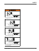
SAFETY Recognize Safety Information General Operational Safety Precautions Safety - Alert Symbol The Safety-Alert Symbol identifies import safety messages on equipment, safety signs, in manuals, or elsewhere. When you see this symbol, be alert to the possibility of personal injury of death. Follow the instructions in the safety message. Read and understand the Owner’s/User’s manual and become thoroughly familiar with the equipment and its controls before operating the dock leveler.
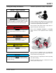
SAFETY Operational Safety Precautions Learn the safe way to operate this equipment. Read and understand the manufacturer’s instructions. If you have any questions, ask your supervisor. Stay clear clear of of dock dockleveling levelingdevice devicewhen whentransport transport vehicle is entering or leaving area. thethe dock leveling device if if Do not not move moveororuse use dock leveling device anyone is under or in front of it. Keep hands hands and and feet feetclear clearofofpinch pinchpoints.
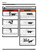
SAFETY Do not use dock leveling device if transport vehicle is too high or too low. Do not overload the dock leveling device. Do not operate any equipment while under the influence of alcohol or drugs. Do not leave equipment or material unattended on dock leveling device.
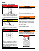
SAFETY Maintenance Safety Precautions ALWAYS disconnect electrical power source and ground wire before welding on dock leveler. DO NOT ground welding equipment to any hydraulic or electrical components of the dock leveler. Always ground to the dock leveler frame. Hydraulic and electrical power must be OFF when servicing the equipment. For maximum protection, use an OSHA approved locking device to lock out all power sources. Only the person servicing the equipment should have the key to unlock the device.
SAFETY Safety Decals Every 90 days (quarterly) inspect all safety labels and tags to ensure they are on the dock leveler and are easily legible. If any are missing or require replacement, please call 1-800-643-5424 for replacements. 5.06" DANGER 2.40" CRUSH HAZARD Maintenance prop must support leveler behind bar. Do not force maintenance prop forward of bar to support lip. Failure to comply will result in death or serious injury. Refer to owner’s/user’s manual for proper use.
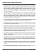
OWNER’S/USER’S RESPONSIBILITIES 1. The owner/ user should recognize the inherent dangers of the interface between the loading dock and the transportation vehicle. The owner/ user should, therefore, train and instruct all operators in the safe operation and use of the loading dock equipment in accordance with manufacturer’s recommendations and industry standards. Effective operator training should also focus on the owner’s/user’s company policies and operating conditions.
GENERAL INFORMATION Dock Leveler Stock Specifications MA-Series dock levelers are available in the following sizes, weight capacities, and options: Width: MA 6 ft (1828.8 mm) 6-1/2 ft (1981.2 mm) 7 ft (2133.6 mm) Length 6 ft (1828.8 mm) 8 ft (2438 mm) 10 ft (3048 mm) Congratulations on your choice of a McGuire dock leveler. This manual covers the Air Bag, MA model air powered dock leveler.
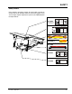
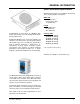
INTRODUCTION Component Identification O A C P N D B J H G K I A — Lip E — Lip Maintenance Prop Pivot) B — Lip Assist Rod F — Lip Actuator Snubber Spring C —Lip Linkage Assembly G — Lip Actuator Chain D — Lip Latch Assembly E F H — Air bag support pallet I — Lip Keepers (2 used) J — Air bag K — Main Frame L M L — Maintenance Prop M —Blower Motor N —Toe Guard (2 used) O —Raise Button P —Safety Legs THEORY The MA dock leveler uses a blower motor and one‑button operation for ease of use.
INTRODUCTION Prepare Pit E A C B 14” 10” D A—Distance (Pit Width) (Front and Rear) B— Distance (Dock Floor-to-Pit Floor) (All Four Corners) C— Distance (Pit Length) (Both Sides of Pit) D— Distance (Pit Corner‑ to‑ Corner) (Top, Bottom, and Both Sides) 1. Before lowering the dock leveler into the pit, the following must be performed: Post safety warnings and barricade the work area at dock level and ground level to prevent unauthorized use of the dock leveler before installation has been completed.
INSTALLATION Prepare Dock Leveler NOTICE A DO NOT remove the shipping bands (B) around the platform lip and leveler frame at this time. The shipping bands are needed to hold the leveler together during the installation process. 1. Remove any control panel and bumpers that may be banded to the frame of the dock leveler. DO NOT remove the shipping bands (B) around the platform lip and leveler frame at this time. NOTICE B A— Lifting Bracket (2 used) DO NOT over tighten the lifting bracket hardware.
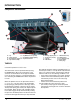
INSTALLATION Shim Stacking Methods Install Dock Leveler N P Q R R A— Distance (Leveler Frame Height) B— Shim Locations (Under Rear Vertical Supports, 4-5 Places TYP) C— Shim Locations (Under Lip Keepers, C —Shim Under Snubber Spring Mount D— Dock Floor E— Rear Pit Curb Angle 4111-0021 — May 2015 F— String G— Rear Hinge Frame Angle H— Distance (Dock Floor-to-Pit Floor) J— Distance (Top of Shim Stack-to-Dock Floor) K— Shim Stack L— Dock Leveler Frame M — Pyramid (Preferred) N— Stepped (Acceptable) P—
INSTALLATION NOTE: McGuire dock levelers are designed with a nominal 1/2 in. (12.7 mm) shimming distance to allow for pit inconsistencies. 1. Determine height of shim stack (L) for each shim location (B) by performing the following: 4. For all MA models, put a 1/4 in. (6.6 mm) thick shim at locations (D). NOTE: A 1/4 in. (6.6 mm) thick shim at locations (D) is used only as a starting point. The final shim stack height will be determined after dock leveler is lowered into the pit. a.
INSTALLATION B A C C D D E F G A— Front of Dock Pit B— Dock Leveler Frame 3/8 in. (9.5 mm) 6 in. (152 mm) C— Side Pit Curb Angle D— Gap [3/4 in. (19 mm) Minimum] 8. With rear hinge frame angle (F) tight against rear pit curb angle (G), perform/check the following: • Pry between the platform and rear hinge frame angle at locations (E) to make sure rear edge of platform is parallel to the rear hinge frame angle (F).
INSTALLATION 12. With the leveler square in the pit and flush with the surrounding dock, remove the banding on the lip of the leveler. 13. Connect the blower motor to the temporary power supply. Two people are required to engage the maintenance prop: one person to operate the lifting device, the other person to engage the maintenance prop. 14. Slowly raise the platform. Check for binding as platform is being raised. 15. If binding occurs, lower the platform.
INSTALLATION NOTICE DO NOT grind or weld if hydraulic fluid or other flammable liquid is present on the surface to be ground or welded. DO NOT grind or weld if uncontained hydraulic fluid or other flammable liquid is present. Stray sparks can ignite spills or leaks near the work area. Always clean up the oil leaks and spills before proceeding with grinding or welding. Always keep a fire extinguisher of the proper type nearby when grinding or welding.
INSTALLATION Install Control Panel and Wiring A The electrical power must be OFF prior to electrical installation. For maximum protection, use an OSHA approved locking device to lock out all power sources. Only the person installing the equipment should have the key to unlock the power source. Failure to follow these instructions may result in serious personal injury or death. D B C DO NOT make any final electrical connections until all welding has been completed.
INSTALLATION Put New Dock Leveler Into Service 1. Disconnect the external lifting device and chains from the lifting brackets. 2. Check that the leveler is flush with the dock floor and that the platform lip contacts both lip keepers evenly. If an excessive transition exists between the dock floor and leveler and/or lip does not contact both lip keepers evenly, contact Technical Services for further instructions. 7. When the platform lowers to the full below-dock position, the lip will fold.
OPERATION Operating Instructions Stay clear of dock leveler when transport vehicle carrier is entering or leaving dock area. 12in. (305mm) DO NOT move or use the dock leveler if anyone is under or in front of leveler. Keep hands and feet clear of pinch points. Avoid putting any part of your body near moving parts. Failure to follow these instructions may result in severe personal injury or death. Only trained personnel should operate the dock leveler. DO NOT use a broken or damaged dock leveler.
OPERATION Operating Instructions—Continued Below Dock Loading/Unloading Instructions Ramp Loading/Unloading Instructions NOTE: If end unloading is required, see End Loading/ Unloading Instructions on page 20. NOTE: If end unloading is required, see End Loading/ Unloading Instructions on page 20. 7. Check to make sure transport vehicle is positioned squarely against dock bumpers. For ramp loading or unloading, the MA dock leveler can be operated by using the RAISE button on the control panel. 8.
OPERATION Operating Instructions—Continued End Loading/Unloading Instructions NOTE: If ramp loading is required, see Ramp Loading/ Unloading Instructions on page 19. End loading or unloading can be done with the dock at the cross-traffic position or below‑dock position, depending on the height of the transport vehicle bed. 1. Check to make sure transport vehicle is positioned squarely against dock bumpers. 2. Instruct driver to remain at the dock until the loading or unloading process has been completed. 3.
MAINTENANCE Service Dock Leveler Safely E When service under the dock leveler is required, always lock all electrical disconnects in the OFF position after raising the platform and engaging the maintenance prop. Failure to do this may result in serious personal injury or death. Always stand clear of the dock leveler lip when working in front of the dock leveler. The maintenance prop MUST be in the service position when working under the dock leveler.
MAINTENANCE Periodic Maintenance A F C B A G C C A— Lip Hinge Area B— Platform hinge area C— Lip prop pivot D— Lip link pivots Under platform service 22 E— Safety leg pivots F— Lip Linkage Pivot G — Safety leg linkage pivots Air Filter, service under rear of platform 4111-0021 — May 2015
MAINTENANCE Quarterly Maintenance Regular maintenance must be performed on a weekly and quarterly schedule. FOLLOW ALL SAFETY PRECAUTIONS Weekly Maintenance • Operate the dock leveler through the complete operating cycle to maintain lubrication. • Lubricate the following areas with white lithium grease: (A)— Lip prop pivot (B)— Lip link pivots NOTE: To thoroughly inspect the platform hinge area, put the platform in the full below‑dock position.
ADJUSTMENTS Adjusting the Latch and Lip Actuator Spring Tension When service under the dock leveler is required, always lock all electrical disconnects in the OFF position after raising the platform and engaging the maintenance prop. Failure to do this may result in serious personal injury or death. Always post safety warnings and barricade the work area at dock level and ground level to prevent unauthorized use of the dock leveler before maintenance is complete.
ADJUSTMENTS Adjusting Lip Latch Spring Tension Adjusting Lip Assist Spring Tension This adjustment is set at the factory and should not require additional adjustment. This adjustment is set at the factory and should not require additional adjustment. Unlike mechanical levelers, the lip will not immediately begin to fold as the platform returns to the stored position. Unlike mechanical levelers, the lip will not immediately begin to fold as the platform returns to the stored position.
ADJUSTMENTS Adjust Lip Stop Bolt Always post safety warnings and barricade the work area at dock level and ground level to prevent unauthorized use of the dock leveler before maintenance is complete. Failure to do this may result in serious personal injury or death. A B Always stand clear of the dock leveler lip when working in front of the dock leveler. Failure to do this may result in serious personal injury or death.
This page intentionally left blank 4111-0021 — May 2015 27
TROUBLESHOOTING When service under the dock leveler is required, always lock all electrical disconnects in the OFF position after raising the platform and engaging the maintenance prop. Failure to do this may result in serious personal injury or death. Always post safety warnings and barricade the work area at dock level and ground level to prevent unauthorized use of the dock leveler before maintenance is complete. Failure to do this may result in serious personal injury or death.
TROUBLESHOOTING Symptom Platform rises slowly Possible Cause Air bladder or connecting ducts punctured Solution Check air bladder and ducting replace as needed Damaged or restricted ducting Replace damaged ducting or remove restriction Air intake clogged Remove intake filter, clean or replace as needed Dock leveler binding Check for visible obstructions that could cause binding. Remove obstructions. If no obstructions found, call Technical Services.
ELECTRICAL 30 4111-0021 — May 2015
PARTS Controls A D 4 -1/2 C 11.8 FLA Amp Draw B 2-7/8 3.00 O P E R AT I N G ! DANGER • • • • • E • • • • • • INSTRUCTIONS Read and follow all instructions, warnings, and maintenance schedules in the manual and on placards. Operation and servicing of dock leveler is restricted to authorized personnel. Always chock transport vehicle wheels or engage vehicle restraint and set parking brakes before operating dock leveler or beginning to load or unload.
PARTS U Lip Activation Before 2012 I H I A B T J D C U I S F G V W X Y E R Q K L O O M P Item A B C D E F G H I J K L M O P Q R S T U V W X Y 32 Quantity 1 1 2 1 1 1 2 1 2 3 1 1 1 1 3 1 1 3 1 1 2 1 1 1 1 Part Number 9514-0107 DPLA-2130 DOTH-2404 DOTH-2076 DOTH-2160 DOTH-2546 DOTH-2225 DPLA-2126 DOTH-2061 DOTH-2131 5775-0004 0941-0013 DOTH-2555 DPLA-2128 2101-0217 2101-0216 DOTH-2421 DOTH-2214 DOTH-2547 DOTP-2006 DOTH-2062 DOTH-2351 DOTH-2163 DOTH-2210 DOTH-2374 Description * * * Lip
PARTS Lip Activation JAN 2012 and Newer A B N C D E F G M J K F L R I H P O P Q Item Quantity A 1 B 1 C 1 D E F G H I J K L M N O P Q R 1 1 1 1 1 1 1 1 3 1 1 1 1 1 1 4111-0021 — May 2015 Part Number DLIP-0305 DOTH-2550 DOTH-2546 5775-0004 5775-0005 DOTH-2351 DOTH-2163 DOTH-2210 DOTH-2374 DPLA-0338 DPLA-0340 DOTH-2131 DOTH-2547 DOTH-2214 DOTH-2062 DOTP-2005 2101-0217 DPLA-2128 DOTH-2555 0941-0013 Description Lip Assist Rod Complete 34” Lg.
PARTS This Page Intentionally Left Blank 34 4111-0021 — May 2015
PARTS Airbag and Support Pallet Item Quantity Part Number 1 3 5812-0045 Hold Down Rod, 45” long x 7/16” diameter 2 1 5811-0009 Air Bag Bladder 3 1 5811-0012 Skid, Air Bag Leveler 4 2 5813-0001 Skid BRKT, Air Bag Leveler, BM 5 4 2101-0098 Screw, HHCS, 5/16-18UNC x 1-1/2 long 6 4 2101-0214 Nut, Flange, Top L/N, 5/16 - 18UNC 7 4 2101-0058 Washer, Lock 5/16 8 6 2101-0224 Rod Clamps 9 4 2101-0079 Washer Flat 1/2 inch 10 2 2101-0230 Ring, Split 1.75 O.
PARTS Frame and Platform Lip latch Release Arm Up Grade. Maybe required on some levers (manufactured before 4/2014) if below dock is required BILL OF MATERIAL ITEM QTY PART NO. DESCRIPTION 1 1 8432-1006 SNUBBER MOUNT AP SERIES 2 1 8432-1212 LIP LATCH RELEASE ARM S Y S T SIZE E M S, P O W E R A M P D L M I N C. L o a d i n g D o c k E q u i p m e n t WLDT, LIP LATCH RELEASE, 2014 MATERIAL DRAWN BY KRV TOLERANCES (UNLESS OTHERWISE NOTED) FRACTIONAL: 1/32" DECIMAL: .00 = .01" .000 = .
PARTS Frame and Platform PLATFORMS1 6 FOOT ITEM QTY 1 6.0 FOOT 6.5 FOOT 7.0 FOOT 8 FOOT 6.0 FOOT 6.5 FOOT 10 FOOT 7.0 FOOT 6.0 FOOT 6.5 FOOT 7.
PARTS 2 1 DPLA-0338 LIP BANGER ASSY. 3 2 DPLA-0340 BAR 4 1 5775-0004 LIP LATCH ASSEMBLY 5 1 DOTH-2374 COTTER PIN 6 2 DOTH-2210 WASHER 7 1 DOTH-2351 BOLT/PIN 8 1 DOTH-2163 NUT, LOCK 9 1 DPLA-0360 BELOW DOCK CONTROL ASSY. 10 2 DOTH-2382 PIN, COTTER 11 1 DOTH-2074 BOLT, HEX 5/8-11 X 2.00 12 1 DOTH-2160 NUT, HEX 5/8-11 17 1 DPLA-0360 BDC PUSH ROD ASSY 18 1 DOTH-2060 BOLT SHOULDER 19 1 DOTH-2131 LOCK NUT 3/8-16 20 1 DLIP-0305 LIP ASSIST ROD ASSY.
PARTS Toe Guard/Weather Seal—Optional E Weather Seal Kits D Item Quantity Part Number A B 1 1 0195-0021 0195-0033 C Description Brush Kit Includes Seal and Track, 1-1/2 in. 82" Lg. (Both Sides) Rubber Kit Includes Seal and Track, 1-1/2 in. 82" Lg. (Both Sides) Individual Replacement Seals Item Quantity Part Number C D E 1 1 1 0192-0098 0192-0085 0192-0146 Description Brush Refill, 1-1/2 in. 82" Lg. Rubber Refill, 1-1/2 in. 82" Lg.
PARTS Motor and Blower Assembly F H D A B D C E Item Quantity Part Number Description A 1 9395-0359 B 1 9391-0021 Filter Element (Included With 9395-0359) 9391-0022 Tube, 2” (50.8mm) OD, 36” (914.4mm) Length 6’ and 8’ Levelers 9391-0041 Tube, 2” (50.8mm) OD, 46” (914.4mm) Length 10’ levelers 9392-0047 Pipe, PVC, 1-1/2” SCH40 X 24” (38.1 X 609.6mm) 9392-0068 Pipe, PVC, 1-1/2” SCH40 X 24” (38.1 X 609.
MISCELLANEOUS Customer Information A NOTE: Refer to illustration for left/right orientation of dock leveler. The model/serial number decal (A) is located on the right platform joist near the front (lip) of dock leveler. When you receive your MA-Series dock leveler, write down the dock leveler model and serial number in the form provided. This will help ensure safe keeping of the numbers in the event the model/serial number decal (A) becomes lost or damaged.
STANDARD PRODUCT WARRANTY SYSTEMS, INC. warrants that its products will be free from defects in design, materials and workmanship for a period of one (1) year from the date of shipment. All claims for breach of this warranty must be made within 30 days after the defect is or can with reasonable care, be detected. In no event shall any claim be made more than 30 days after this warranty has expired.