Parts Manual REGENT / 500 / 2500 SERIES LAWN TRACTORS & MOWER DECKS 12.5HP GEAR TRACTORS 36” MOWER DECKS Mfg. No. Description 1692366 1692410 1692401 1692405 1692409 1692493 Regent 12.5HP Gear Regent 12.5HP Gear (Export) 512G, 12.5HP Gear 2513G, 12.5HP Gear 36” Mower Deck 36” Mower Deck 12.5HP HYDRO TRACTORS Mfg. No. Description 1692403 1692407 1692412 1692495 Regent 12.5HP Hydro Regent 12HP Hydro (Export) 512H, 12HP Hydro 2512H, 12HP Hydro Rev.
MANUFACTURING, INC. 500 N Spring Street / PO Box 997 Port Washington, WI 53074-0997 USA © Copyright 1995 Simplicity Manufacturing, Inc. All Rights Reserved. Printed In USA.
Table of Contents FRAME................................................................................................................................................................2 FRONT AXLE .....................................................................................................................................................4 STEERING ..........................................................................................................................................................
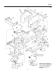
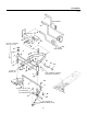
Frame **2405 3 42 20 6 31 30 42 36 40 31 30 9 30 11 28 31 26 21 Hydro Models 22 Only 2 24 42 45 19 16 18 36 30 7 13 39 17 8 23 37 29 38 38 10 4 11 5 29 33 38 25 38 26 35 Assemble screw in this location with head to the inside. 43 44 12 27 44 1 14 34 41 13 15 34 2 NOTE: Unless noted otherwise, use the standard hardware torque specification chart.
All Models Frame REF. NO. PART NO. QTY.
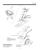
Front Axle **1513 Hydro Models 17 11 Grease 26 Ref. No. 7 includes Ref. Nos. 2 & 3 11 10 1 12 8 16 Gear Models 8 4 3 23 28 3 2 7 13 18 3 19 21 27 Torque to 45-62 ft. lbs. 14 22 23 4 20 Lube spindle thru fittings with grease (2 places) 3 27 5 6 20 9 24 6 25 Torque to 15-25 ft. lbs.
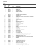
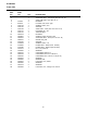
All Models Front Axle REF. NO. 1 2 3 4 5 6 7 8 9 10 11 12 13 14 15 16 17 18 19 20 21 22 23 24 25 26 27 28 PART NO. QTY. DESCRIPTION 176440 921133 1611703 1611705 1611708 1611710 1611715 1663114 1664847 1665601 1668147 1671260 1705918 1709305 1709785 1917372 1919326 1921210 1921333 1921525 1924361 1924940 1930651 1960020 1960114 1960362 1 1 4 2 1 2 1 2 1 1 5 1 1 1 1 1 1 1 1 2 1 1 2 2 2 1 2 1 SUPPORT ASSY., Axle, Rear (See Ref. No. 12) AXLE SUB ASSY. (See Ref. No.
Steering **51 13 4 15 9 2 10 16 19 5 Coat gear teeth with grease. 2 2 2 16 Torque to 8 13-19 ft. lbs. 3 18 Torque to 17-23 ft. lbs. 6 7 Torque to 50-55 ft. lbs. NOTE NO. 1 loosen jam nut (Ref. No. 14) and index drag link (Ref. No. 1) to correct angle; torque jam nut to 13 ft. lbs. NOTE: Unless noted otherwise, use the standard hardware torque specification chart. See the Table of Contents. 1 14 11 17 See Front Wheels & Tires for assy.
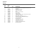
All Models Steering REF. NO. PART NO. QTY. DESCRIPTION 1 2 3 4 5 6 7 8 9 10 11 12 13 14 15 16 17 18 19 176440 1652743 1667513 1667622 1668927 1674076 1675388 1686651 1701266 1705437 1705914 1714097 1919262 1921332 1928721 1930245 1935048 1960540 1 5 1 1 1 1 1 1 1 1 1 1 1 1 4 2 1 4 1 LINK, Drag (Not Serviced Separately. See Ref. No. 14) BUSHING BASE PLATE, Steering TOP PLATE, Steering KEY LOCKNUT, Center, 3/8-24 ROD, Steering GEAR, Steering STEERING WHEEL, 13-1/2" (Incl. Ref. Nos. 13 & 19) SHAFT ASSY.
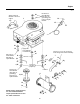
Engine **271 RH Rear on Gear Models (Zinc pltd. for grounding); RH Front on Hydro Models. 28 Apply sealant to threads. Locknut to engine. 4 1 8 16 15 5 12 27 22 25 RH Front on Gear Models; RH Rear on Hydro Models. Apply antiseize lubricant to crankshaft. 22 Torque to 7-11 ft. lbs. (2 places) Coat with grease before assembly 25 22 22 LH Front 10 2, 3 23 2, 3 21 23 6, 25 RH Rear on Gear Models (Zinc pltd. for grounding); RH Front on Hydro Models. 7 Torque to 20-30 ft. lbs.
All Models Engine REF. NO. PART NO. QTY. DESCRIPTION 1 2 3 4 5 6 7 8 9 10 11 12 13 14 15 16 17 18 19 20 21 22 23 24 25 26 27 28 * 158499 172844 920427 960241 960361 1650670 1655405 1655848 1655860 1657118 1667346 1674163 1676183 1707388 1713846 1917356 1917372 1918199 1919326 1921332 1924356 1924940 1928038 1930598 1931342 1932849 1960251 1 2 2 1 2 1 1 1 1 1 1 1 1 1 1 1 5 3 1 1 2 6 2 1 3 1 1 1 ENGINE, 12.5 HP STOP, Belt (Hydro models) STOP, Belt (Gear models) LOCKWASHER, Ext., 3/8, Zinc Pltd.
Gear Transaxle **2370 16 41 31 24 30 9 28 33 35 37 15, 39 Torque to 14-21 ft. lbs. Attach to inside of rear wrapper 42 10 8 37 .25 ± .03 clearance between pulley hub & snap ring on trans. 21 34 12 Use washers as req'd to adjust shift lever to neutral slot. 26 46 25 hours. NOTE: Unless noted otherwise, use the standard hardware torque specification chart. See the Table of Contents. 49 40 45 4 46 24 19 Lubricate every 21 44 Slide each bracket (Ref. No. 6) towards center of transaxle.
Mfg. Nos. 1692401, 1692405, 1692409, 1692493 Gear Transaxle REF. NO. PART NO. QTY.
Hydro Transaxle - Group 1 **2566 20 26 29 8 30 16 13 2 10 27 6 21 5 4 22 See Rear Wheels & Tires for assy. parts & mounting hardware 32 31 5 19 4 1 23 24 7 28 11 9 3 12 17 30 14 15 20 28 NOTE: Unless noted otherwise, use the standard hardware torque specification chart. See the Table of Contents.
Mfg. Nos. 1692403, 1692407, 1692412, 1692495 Hydro Transaxle - Group 1 REF. NO. PART NO. QTY.
Hydro Transaxle - Group 2 **2567 10 13 12 13 12 21 19 22 8 16 15 2 1 24 2 12 21 7 5 5 21 2 18 11 6 13 3 2 14 12 15 23 4 17 9 NOTE: Unless noted otherwise, use the standard hardware torque specification chart. See the Table of Contents.
Mfg. Nos. 1692403, 1692407, 1692412, 1692495 Hydro Transaxle - Group 2 REF. NO. PART NO. QTY. DESCRIPTION 1 2 3 4 5 6 7 8 9 10 11 12 13 14 15 16 17 18 19 20 21 22 23 24 1666697 1704428 1707424 1709227 1709775 1709776 1709777 1709782 1709784 1709824 1713843 1917356 1917372 1918447 1919326 1919381 1921333 1924361 1924856 1924940 1925003 1931335 1931337 1960170 1 4 1 1 2 1 1 1 1 1 1 3 3 3 4 1 1 1 4 1 4 1 1 1 SPACER BUSHING SPRING, Torsion SPACER BRACE, Shift Panel ROD, Shift SHIFT ROD ASSY.
Brake & Clutch - Gear Models **50 21 20 Between frame & head of stud (Ref. No. 2) 2 22 23 25 Idler Assy. must pivot freely with .015" maximum end play. 4 26 29 6 14 5 27 3 8 12 Grease pedal shaft and insert damper (Ref. No. 8) into pedal groove before assembling pedal (Ref. No 5). Small end of spring 15 13 Clutch Rod Brake Rod 32 30 24 7 17 Grease 22 23 10 28 19 18 Install in lower brake cam lever hole.
Mfg. Nos. 1692401, 1692405, 1692409, 1692493 Brake & Clutch - Gear Models REF. NO. PART NO. QTY.
Brake & Clutch - Hydro Models **2568 18 20 1 10 13 2 24 12 Transmission Brake Arm 19 23 8 21 27 22 9 4 14 16 29 17 11 Lubricate bushings (Ref. No. 4) with grease. 4 15 26 Hook in center slot - 6 rear of steering sump 19 26 26 26 NOTE: Unless noted otherwise, use the standard hardware torque specification chart. See the Table of Contents. 3 21 5 7 29 25 28 18 28 Apply anti-seize lubricant to Ref. No. 5 before assy.
Mfg. Nos. 1692403, 1692407, 1692412, 1692495 Brake & Clutch - Hydro Models REF. NO. PART NO. QTY.
Electrical - Gear Models **2413 Slide boot over terminal after securing to battery. 32 14 33 10 31 12 20 7 27 NOTE: Apply grease to ignition switch terminals (Ref. No. 14) and wire harness plug before connecting. 36 29 28 13 30 18 26 21 Place end of hose through hole in frame. 25 19 Mount in frame Zinc. Pltd. 22 16 2 To Operator Present Seat Switch 24 34 9 8 34 17 29 30 Zinc Pltd.
Mfg. Nos. 1692401, 1692405, 1692409, 1692493 Electrical - Gear Models REF. NO. PART NO. QTY.
Electrical - Hydro Models **2412 Slide boot over terminal after securing to battery. 32 11 9 33 15 32 21 6 Maximum torque of 22 in.-lbs. 28 29 30 Apply grease to ignition switch terminals (Ref. No. 14) and wire harness plug before connecting. 22 26 36 27 19 12 31 Place end of hose thru hole in frame. 18 Mount in frame. Ground 2 23 14 13 34 To Operator Present Seat Switch. 8 34 Zinc Pltd.
Mfg. Nos. 1692403, 1692407, 1692412, 1692495 Electrical - Hydro Models REF. NO. PART NO. QTY.
Hood, Grille, Dash & Fuel Tank **2424 2 27 Torque to 20-30 in. lbs. 35 45 24 37 36 31 5 12 17 14 Brace (Ref. No. 6) must be assembled parallel to this surface. 18 15 13 1 4 7 44 26 30 25 29 31 16 33 20 21 28 23 42 39 11 44 33 32 34 6 44 40 41 8 42 22 10 38 19 3 NOTE: Unless noted otherwise, use the standard hardware torque specification chart. See the Table of Contents. 24 43 Torque to 20-30 in lbs.
All Models Hood, Grille, Dash & Fuel Tank REF. NO. PART NO. QTY.
Seat & Deck **1307 15 17 18 18 21 1 8 1 16 24 21 23 29 26 6 2 5 3 23 30 12 Hydro Models 4 27 7 19 21 13 20 Gear Models Seat supports must pivot freely when assembled 23 9 28 25 10 22 14 29 23 27 11 27 28 26 NOTE: Unless noted otherwise, use the standard hardware torque specification chart. See the Table of Contents.
All Models Seat & Deck REF. NO. PART NO. QTY. DESCRIPTION 1 2 3 4 5 6 7 8 9 10 11 12 930222 1666690 1666691 1668839 1678415 1701229 1701252 1701560 1701736 1701737 1701742 1702690 41702690 1709775 1709824 1713839 1714320 1714482 1714494 1917356 1917372 1919326 1919438 1921332 1923701 1924856 1925205 1927557 1928729 1930651 1931333 2 2 2 1 2 1 2 2 1 1 2 1 1 2 1 1 1 1 1 2 2 4 2 10 2 4 4 8 2 2 2 CLIP SPRING, Seat COVER, Wire PANEL, Shift (Gear models) HINGE, Lower BUSHING, Snap SEAT LATCH ASSY.
Front Wheels & Tires Grease front wheel assemblies. 8 10 1 5 9 2 3 9 4 6 7 NOTE: Unless noted otherwise, use the standard hardware torque specification chart. See the Table of Contents.
All Models Front Wheels & Tires REF. NO. PART NO. QTY. 1 2 3 4 5 6 7 172353 912808 960202 1611710 1664090 1673333 1709856 2 2 2 2 2 2 2 8 9 10 1713166 1713167 1713168 2 4 2 11 1714428 2 DESCRIPTION VALVE STEM & CAP FITTING, Grease WASHER, 3/4 KLIP RING, 3/4 TUBE, Front Wheel, 4.10/3.50-6 HUB CAP (AGCO & Massey Ferguson models only) FRONT WHEEL & TIRE ASSY., Metallic Gray, 15 x 6.00-6 (Incl. Ref.Nos. 1, 8 & 10) TIRE, Front Wheel, 15 x 6.00-6 BEARING FRONT WHEEL ASSY., Metallic Gray, (Incl. Ref.
Rear Wheels & Tires 5 Qty. 1 or 2 (As required left wheel only) 1 9 4 9 2 6 7 NOTE: Unless noted otherwise, use the standard hardware torque specification chart. See the Table of Contents.
All Models Rear Wheels & Tires REF. NO. PART NO. QTY. DESCRIPTION 1 2 3 4 5 172353 927794 1676519 1701435 1709857 2 2 2 2 2 6 7 8 9 1713170 1713171 1714429 1960114 2 2 2 2 VALVE STEM & CAP E-RING HUB CAP (AGCO & Massey Ferguson models) RETAINER, Hub Cap (AGCO & Massey Ferguson models) REAR WHEEL & TIRE ASSY., Metallic Gray, 18 x 8.50-8 (Incl. Ref. Nos. 1, 5 & 6) TIRE, Rear Wheel, 18 x 8.50-8 REAR WHEEL ASSY., Metallic Gray, 18 x 8.
Decals - Simplicity Models Located underneath hood 12 17, 18, 20 16 17, 18, 19 9 Located on LH side 10 of wrapper to the right of the release lever. 4 Located on LH side of wrapper above transmission fan. 6 14 13 11 2 7 8 3 1 NOTE: Unless noted otherwise, use the standard hardware torque specification chart. See the Table of Contents.
Simplicity Models Decals REF. NO. PART NO. 1 2 3 4 5 6 7 8 9 10 11 12 13 14 15 16 17 18 19 20 1656855 1668202 1701270 1704276 1702944 1704277 1704910 1708277 1708918 1708927 1709061 1709371 1709387 1709861 1713550 1713966 1713967 1713968 1713969 QTY.
Decals - AGCO Allis Models Located underneath hood 15 19 8, 10, 17 9, 11,16 7, 18 Located on LH side 12 of wrapper to the right of the release lever. 3 Located on LH side of wrapper above transmission fan. 17 16 14 2 5 6 13 1 NOTE: Unless noted otherwise, use the standard hardware torque specification chart. See the Table of Contents.
AGCO Allis Models Decals REF. NO. PART NO. 1 2 3 4 5 6 7 8 9 10 11 12 13 14 15 16 17 18 19 1656855 1701270 1701270 1704277 1704910 1708276 1708820 1708821 1708823 1708824 1708918 1708926 1708927 1709061 1709371 1709387 1709861 1713550 QTY.
Decals - Massey Ferguson Models Located underneath hood 13 15, 17 16, 18 7, 13 8 Located on LH side of wrapper to the right of the release lever. 3 Located on LH side of wrapper above transmission fan. 14 11 10 9 2 5 6 14 1 NOTE: Unless noted otherwise, use the standard hardware torque specification chart. See the Table of Contents.
Massey Ferguson Models Decals REF. NO. PART NO. 1 2 3 4 5 6 7 8 9 10 11 12 13 14 15 16 17 18 1656855 1701270 1704276 1704277 1704910 1708277 1708918 1708927 1709371 1709387 1709861 1713550 1714363 1714368 1714369 1714370 1714371 QTY.
36" Mower Deck - Deck, Arbor & Blades **54 32 33 Torque to 50-70 ft. lbs. (2 places). 47 31 50 Torque to 50-70 ft. lbs. 43 48 44 36 18 7 26 45 40 12 46 5 46 37 41 11 42 46 1 37 17 30 22 46 34 46 35 1 42 27 20 49 51 46 28 Torque to 15-19 ft. lbs. (2 places). 21 2 3 51 Apply gasket former to this surface, unless foam gasket (Ref. No. 30) is used. 29 25 24 42 15 51 6 48 48 19 16 4 10 9 13 14 46 8 39 38 Torque to 50-70 ft. lbs.
All Models 36" Mower Deck - Deck, Arbor & Blades REF. NO. PART NO. QTY.
36" Mower Deck - Deck, Arbor & Blades **54 32 33 Torque to 50-70 ft. lbs. (2 places). 47 31 50 Torque to 50-70 ft. lbs. 43 48 44 36 18 7 26 45 40 12 46 5 46 37 41 11 46 42 1 37 17 23 30 22 46 34 46 35 1 42 27 20 49 51 46 28 Torque to 15-19 ft. lbs. (2 places). 21 2 3 51 Apply gasket former to this surface, unless foam gasket (Ref. No. 30) is used. 29 25 24 42 15 51 6 48 48 19 16 4 10 9 13 14 46 8 39 38 Torque to 50-70 ft. lbs.
All Models 36" Mower Deck - Deck, Arbor & Blades REF. NO. PART NO. QTY. DESCRIPTION 43 44 45 46 47 48 49 50 51 1930584 1930585 1931211 1931277 1931317 1931333* 1931348 1933263 1960373 1 2 2 9 1 6 2 2 12 CAPSCREW, Hex Hd., 7/16-14 x 2-3/4 CAPSCREW, Hex Hd., 7/16-14 x 3-1/2 NUT, Hex, Flange, Whizlock, 3/8-16 NUT, Hex, Flange, Whizlock, 5/16-18 CARRIAGE BOLT, 1/4-20 x 3/4 CARRIAGE BOLT, 5/16-18 x 3/4 CARRIAGE BOLT, 3/8-16 x 3/4 WASHER, 29/64 x 1-1/4 x 1/4 SCREW, Hex, Wash. Hd.
36" Mower Deck - Clutch & Roller Support **55 54 26 53 10 29 23 40 16 14 53 44 Minimum .03" clearance between items 33 and 34 when brake is engaged. 41 34 Grease 30 19 31 50 44 P.T.O. Rod 43 48 20 32 (see 36" roller & misc. group) 33 22 7 11 1 49 21 19 27 37 39 9 47 17 Coat O.D. with anti-seize lubricant.
All Models 36" Mower Deck - Clutch & Roller Support REF. NO. PART NO. 1 2 3 4 5 6 7 8 9 10 11 12 13 14 15 16 17 18 19 20 21 22 23 24 25 26 27 28 29 30 31 32 33 34 35 36 37 38 39 40 108157 108512 108662 108717 154177 159159 163103 171320 176933 910542 924356 1653768 1654655 1655811 1656412 1656991 1657242 1663114 1663222 1663223 1664004 1666294 1668098 1668099 1669232 1669233 1674011 1677135 1677750 1685150 1701532 1701535 1701536 1702341 1702502 1707563 1916950 1918447 1918452 QTY.
36" Clutch & Roller Support Group **55 54 26 53 10 29 23 40 16 14 53 44 Minimum .03" clearance between items 33 and 34 when brake is engaged. 41 34 Grease 30 19 31 P.T.O. Rod 44 (see 36" roller & misc. group) 50 48 20 43 32 33 22 7 11 1 49 21 19 27 37 39 9 47 17 Coat O.D. with anti-seize lubricant.
All Models 36" Mower Deck - Clutch & Roller Support REF. NO. PART NO. 41 42 43 44 45 46 47 48 49 50 51 52 53 54 55 56 57 1919326 1920564 1921971 1922755 1923087 1923220 1923362 1924856 1924940 1924940 1928804 1928957 1930645 1931277 1931333 1960074 8191022 QTY. 4 6 1 2 2 2 1 4 1 1 1 1 4 14 8 3 1 DESCRIPTION WASHER, Plain CARRIAGE BOLT, 5/16-18 x 1-1/4 CAPSCREW, Hex Hd., 3/8-16 x 1-3/4 WASHER, Plain PIN, Clevis CARRIAGE BOLT, 3/8-16 x 1-1/4 LOCKNUT, Hex, 5/16-18 SCREW, Hex Hd.
36" Mower Deck - Roller & Misc. Group **56 10 16 5 11 16 12 1 9 8 15 7 4 15 Assemble rolllers with ribs to inside as shown. 14 Attach chain to right side of mower lift arm. 6 13 15 4 15 1 1 15 4 15 15 3 4 15 2 2 NOTE: Unless noted otherwise, use the standard hardware torque specification chart. See the Table of Contents.
All Models 36" Mower Deck - Roller & Misc. Group REF. NO. PART NO. QTY. DESCRIPTION 1 2 3 4 5 6 7 8 9 10 11 12 13 14 15 16 153124 156306 176012 1668487 1668744 1669241 1673574 1673575 1685243 1713549 1918448 1920161 1921333 1935048 1960020 1960074 4 2 2 4 1 1 1 1 1 1 1 1 1 1 8 2 RING, Retaining PIN CLIP, Safety ROLLER ROD, P.T.O. CHAIN, Lift 4 Links PIN, Rivet CLEVIS, Pin ROD, Lift V-BELT, Mower Drive PIN, Cotter, 3/32 x 1 NUT, Jam, 5/16-18 CAPSCREW, Hex Hd.
Gear Transaxle Service Parts - Peerless Model 930-039 68 34 29 8 7 9 31 8 5 23 85 2 32 29 12 28 71 22 72A 25 49 31 34 1 31 81 52 30 53 4 69 47 14 17 26 85 50 30 83 29 13 21 20 66 67 6 27 29 2 10 11 58 26 15 14 59 31 90 37 41 39 38 150 MODEL and SERIAL NUMBERS HERE 45 NOTE: Unless noted otherwise, use the standard hardware torque specification chart. See the Table of Contents.
Mfg. Nos. 1692401, 1692405, 1692409, 1692493 Gear Transaxle Service Parts - Peerless Model 930-039 REF. NO. PART NO. QTY.
Hydro Transaxle Service Parts - Hydro Gear Model 318-0500 12 11 17 10 16 9 18 19 13 8 7 6 3 5 3 2 4 NOTE: Unless noted otherwise, use the standard hardware torque specification chart. See the Table of Contents.
Mfg. Nos. 1692403, 1692407, 1692412, 1692495 Hydro Transaxle Service Parts - Hydro Gear Model 318-0500 REF. NO. PART NO. 1 2 3 4 5 6 7 8 9 10 11 12 13 14 15 16 17 18 19 1709907 1709908 1709909 1709910 1709911 1709912 1709913 1709914 1709915 1709917 1709918 1709919 1709920 1709921 1709922 1713322 1713323 1713324 1713617 QTY. 1 1 2 1 1 1 1 1 2 1 1 1 1 1 1 1 1 1 1 DESCRIPTION ARM, Bypass SEAL PUCK, Dampener SETSCREW ARM, Control SPRING CUP WASHER SCREW, Socket Hd.
INDEX Part No. 108157 108202 108512 108662 108717 122023 122023 122184 122184 153124 154177 156302 156306 157041 157127 157273 158499 159106 159106 159159 163103 165073 165073 170164 171252 171320 172353 172353 172434 172434 172844 173206 176012 176933 510334 770102A 772107B 774869 774927 776135 776219A 776260 776315A 778068 778113A 778122A 778123A 778124A 778126A 778127A 778128A Ref. No. & Page No.
INDEX Part No. 1674358 1674669 1676375 1676519 1676861 1677135 1677135 1677296 1677296 1677370 1677371 1677750 1678100 1678339 1678415 1685102 1685150 1685150 1685215 1685215 1685243 1685245 1685251 1685290 1685290 1685297 1686609 1686613 1686637 1686637 1700229 1700230 1700472 1700472 1701229 1701252 1701270 1701270 1701270 1701270 1701435 1701522 1701522 1701532 1701535 1701536 1701555 1701560 1701580 1701580 1701736 INDEX Ref. No. & Page No.
INDEX Part No. 1714055 1714055 1714320 1714363 1714368 1714369 1714370 1714371 1714428 1714429 1714482 1714494 1916622 1916622 1916622 1916950 1916950 1916950 1916964 1916964 1916964 1916964 1916965 1916965 1916966 1917356 1917356 1917356 1917356 1917356 1917356 1917356 1917356 1917356 1917372 1917372 1917372 1917372 1917372 1917372 1917372 1918196 1918199 1918199 1918213 1918447 1918447 1918447 1918447 1918447 1918447 Ref. No. & Page No.
Hardware Identification & Torque Specifications Common Hardware Types Torque Specification Chart Hex Head Capscrew FOR STANDARD MACHINE HARDWARE (Tolerance ± 20%) Washer Hardware Grade Lockwasher Carriage Bolt No Marks SAE Grade 2 Hex Nut Size Of Hardware Standard Hardware Sizing 8-32 8-36 10-24 10-32 1/4-20 1/4-28 5/16-18 5/16-24 3/8-16 3/8-24 7/16-14 7/16-20 1/2-13 1/2-20 9/16-12 9/16-18 5/8-11 5/8-18 3/4-10 3/4-16 7/8-9 7/8-14 1-8 1-12 When a washer or nut is identified as 1/2”, this is the