Print Vendor Instructions Paper Size: How to use this file Operator’s Manuals • 11x17 • Body - 50 lbs brilliant white offset or equivalent. • Cover - on pre-printed two tone “Swash” stock. Press: • Body - 1 color, 2-sided • Cover - 1 color, 1 sided Bindery: • Saddle stitch, face trim *if too thick for saddle stitch, tape bind Covers: • FRONT COVER is present at the beginning of the file. • BACK COVER is the page immediately after the front cover.
THIS PAGE INTENTIONALLY BLANK (FOR PLACEMENT ONLY - DO NOT PRINT)
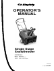
OPERATOR’S MANUAL Single Stage Snowthrower 522E Models Mfg. No.
Table of Contents CONTENTS: Regular Maintenance Safety Rules & Information Lubrication ............................................................16 General ...................................................................2 Training ...................................................................4 Preparation .............................................................4 Operation ................................................................4 Children............................................
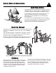
Safety Rules & Information Operating Safety Congratulations on purchasing a superior-quality piece of lawn and garden equipment. Our products are designed and manufactured to meet or exceed all industry standards for safety. Power equipment is only as safe as the operator. If it is misused, or not properly maintained, it can be dangerous! Remember, you are responsible for your safety and that of those around you. Use common sense, and think through what you are doing.
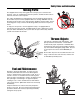
Safety Rules and Information Moving Parts This equipment has many moving parts that can injure you or someone else. However, if you are standing in the operator’s position, and follow all the rules in this book, the unit is safe to operate. The auger and impeller have spinning parts that can amputate hands and feet. Do not allow anyone near the equipment while it is running! DO NOT clear the discharge chute by hand.
Safety Rules & Information This machine is capable to amputating hands and feet and throwing objects. Read these safety rules and follow them closely. Failure to obey these rules could result in loss of control of unit, severe personal injury or death to you, or bystanders, or damage to property or equipment. The triangle in text signifies important cautions or warnings which must be followed. TRAINING OPERATION 1.
Safety Rules 8. Always follow the engine manual instructions for storage preparations before storing the unit for both short and long term periods. 9. Always follow the engine manual instructions for proper start-up procedures when returning the unit to service. 10. Maintain or replace safety and instruction labels as necessary. 11. Keep nuts and bolts tight and keep equipment in good condition. 12. Never tamper with safety devices.
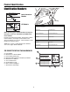
Product Identification Identification Numbers SA Product Identification Tag Model / Modéle / Model M xxxxxxxxxx PL Serial / Sèrie / Serie North American Models xxxxxxxx E Briggs & Stratton Power Products Group, L.L.C. Milwaukee, WI 53201 USA ID Tag Part No. xxxxxxx SA M xxxxxxxxxxxxxxx Serial No. xxxxxxxxxx CE Models xxx PL 20xx E xxxxxxxxxxxxxxxxxxxxxxx xxxxxxxxxxxxxxxxxxxxxxx xxxxxxxxxxxxxxxxxxxxxxx xxxxxxxxxxxxxxxxxxxxxxx PRODUCT dB kg: xxx kW: x.
Product Identification SAFETY DECALS Safety warning decals are placed at strategic locations on the snowthrower as a constant reminder to the operator of the most important safety precautions. All warning, caution and instructional messages on your snowthrower should be carefully read and obeyed. If any of these decals are lost or damaged, replace them at once. They can be purchased from your local dealer. Part No. 1740428MA North American - Danger / Warning Main Dash Decal Part No.
Assembling the Snowthrower TOOLS REQUIRED A • Knife E F REMOVAL FROM CARTON B C 1. Locate and remove container of oil. D 2. Locate all parts packed separately and remove from carton. C NOTE: Set the fuel stabilizer aside until adding gasoline to the fuel tank. We recommend that fuel stabilizer be added to the fuel each time that gasoline is added to the fuel tank. 3. Remove and discard the packing material from around the snowthrower. 4.
Assembling the Snowthrower A A C B B C Figure 3. Z-Hook Installation A. Auger Drive Lever B. Z-Hook C. Auger Drive Cable Figure 4. Upper Chute Installation A. Upper Chute B. T-Knob C. Lower Chute 2. Attach the auger drive cable (C, Figure 3) to the auger drive lever (A) using the Z-hook (B). 3. Remove the T-knob (B, Figure 4) and bolt on the upper chute. 4. Rotate the upper chute (A) to the operating position (past the lower chute stop) 5. Install the bolt and tighten the T-knob (B). A Engine C 1.
Controls & Operation SNOWTHROWER CONTROLS A Auger Control B A. Auger Control - This control engages and disengages the auger. Pull the control back against handle to engage the auger, (this will pull snowthrower forward if auger is in contact with the ground). Release the Auger Control to stop rotation of auger. C Deflector Controls B. Chute Direction Control - The Chute Direction Control (B, Figures 6 & 7) allows the discharge chute to be rotated to throw snow in the desired direction.
Controls & Operation ENGINE & STARTING CONTROLS NOTE: This snow thrower does NOT have a throttle for controlling operating speed of engine. The engine governor maintains operating speed for varying snow removal conditions. B A. Electric Start Button - The Electric Start Button (A, Figure 8) activates an electric starter mounted to the engine, eliminating the need to pull the starter handle.
Controls & Operation GENERAL OPERATION WARNING CHECKS BEFORE EACH START-UP OPERATIONAL WARNINGS 1. Make sure all safety guards are in place and all nuts, bolts and clips are secure. Clearing The Discharge Chute To avoid serious injury, do not put your hands into the auger housing or discharge chute. If the auger stalls or chute becomes plugged, use the following procedure to remove objects or clear the chute: 1. Release the auger control. 2. Shut off the engine. 3. Remove the key. 4.
Controls & Operation ADDING ENGINE OIL 1. Make sure the unit is level. Use a high quality detergent oil classified “For Service SG, SH, SJ, SL, or higher”. A 2. Remove the oil fill cap/dipstick access panel (A, Figure 9). C 2. Remove the oil fill cap/dipstick (B) and wipe with a clean cloth. 3. Insert the oil fill cap/dipstick (B) and turn clockwise to tighten. 4. Remove the oil fill cap/dipstick (B) and check the oil. NOTE: Do not check the level of the oil while the engine is running. B 5.
Controls & Operation STARTING THE ENGINE 7. Disconnect power cord from household receptacle and then from starter switch on snowthrower. Store cord in a dry, convenient place. NOTE: The snowthrower engine is designed to operate at cold temperatures. Avoid operating the snowthrower if air temperature is 40° For warmer since engine may vapor lock and stop running after a short time. Engine will be difficult to start in warm weather. 8. To stop engine, turn engine key to the OFF position.
Controls & Operation OPERATING THE SNOWTHROWER Always be alert to hidden hazards that might be struck by the auger. Should a foreign object be struck by the auger, immediately stop the engine and inspect machine for any damage. Repair damage before continuing operation. Before operating snowthrower, review the Checks Before Each Use under General Operation on page 12 of this manual. 1. Rotate the discharge chute to the desired direction. AFTER EACH USE 2.
Regular Maintenance WARNING Before beginning any repair stop the engine, remove the key, disconnect the spark plug wire, and wait for all moving parts to stop. LUBRICATION NOTE: The drive pulley end of auger shaft is supported by a sealed ball bearing and requires no lubrication. The ball bearing on other end of auger shaft is also sealed, and will not require lubrication. Lightly Oil • A few drops of oil should be placed on wheel hubs occasionally to keep wheels turning freely. Figure 10.
Troubleshooting & Service TROUBLESHOOTING Problem Possible Cause Remedy Engine fails to start 1. Key is OFF 2. Failure to prime cold engine 3. Out of fuel 4. Choke OFF - cold engine 5. Engine flooded 6. Spark Plug not sparking 1. Turn Key to the ON position 2. Press primer button twice and restart. 3. Fill fuel tank 4. Turn Choke to ON. 5. Turn Choke to OFF; try starting 6. Check Gap. Gap plug, clean electrode, or replace as necessary 7. Drain tank (Dispose of fuel at an authorized waste facility).
Troubleshooting & Service COVER REMOVAL AND INSTALLATION REMOVE THE BELT COVER 1. Remove the screws (B, Figure 13) and nuts that hold the belt cover (E) to the auger housing. To access the drive system or the engine, the covers must be removed as follows: REMOVE THE TOP COVER 2. If the top cover (D) has not been removed, then remove the screws (C) that attach the belt cover to the top cover. 1. Remove the discharge chute. See “Chute Removal and Installation”. 3.
Troubleshooting & Service REPLACE DRIVE BELT The drive belt is of special construction and must be replaced with original factory replacement belt available from your nearest dealer. A F 1. Remove the belt cover. See “Remove The Belt Cover”. B E 2. Remove the drive belt (E, Figure 14) from the idler pulley (G). 3. Move the belt guide (B) away from the drive belt (E). C 4. To reduce pressure on the drive belt (E), move the idler pulley (G) away from the belt.
Troubleshooting & Service SERVICING THE SPARK PLUG 1. Remove engine key from switch. 2. Remove the oil access cover. 3. Disconnect the wire from the spark plug. 4. Inspect the spark plug and clean. If necessary, replace it with a new spark plug as recommended in the engine Owner’s Manual. 5. Adjust the gap on the spark plug to .030 inches (.762 mm) using a gauge. Spark Plug Wire 6. Reinstall the plug and tighten firmly, torque to 18-23 ft-lbs (24.4-31.2 Nm). 7. Reconnect spark plug wire. Figure 16.
Troubleshooting & Service AUGER DRIVE CABLE ADJUSTMENT The auger drive cable is adjusted at the factory and no adjustment should be necessary. If the cable becomes stretched or is sagging, adjustment will be necessary. A Whenever the belt is adjusted or replaced, the cable will need to be adjusted. B 1. Remove the Z-hook (C, Figure 18) from the auger drive lever (A). C 2.
Specifications NOTE: Specifications are correct at time of printing and are subject to change without notice. * The gross power rating for individual gas engine models is labeled in accordance with SAE (Society of Automotive Engineers) code J1940 (Small Engine Power & Torque Rating Procedure), and rating performance has been obtained and corrected in accordance with SAE J1995 (Revision 2002-05). Torque values are derived at 3060 RPM; horsepower values are derived at 3600 RPM.
www.SimplicityMfg.com Briggs & Stratton Power Products Group, L.L.C. Copyright © 2008 Briggs & Stratton Corporation Milwaukee, WI USA. All Rights Reserved www.BRIGGSandSTRATTON.