OPERATOR’S MANUAL LANDLORD & SOVEREIGN MFG. MFG. MFG. MFG. NO. NO. NO. NO.
Safety Ge”e‘d Read the Operating and Service lnstrudfions carefully. Be thoroughly familiar with the controls and the proper use of fhe equipment. Never allow children to operate the machine. Do not allow adults to operate it without proper instruction. . When using any attachments, never direct discharge of material toward bystanders nor allow anyone near the vehicle while in operation. . Make sure a. tractor and attachments are in good operating condition, b.
Congratulations on your purchase of the Simplicity tractar. We know you bought this machine to make your lawn and garden work easier. You bought the right machine to do it. So that you can get the very most from your pmchase, we would consider it a personal favor if you would take time to study this manual before using your tractor and its attachments. It will increase the chance of adding you to our long list of satisfied customers.
PROTECT n YOURSELF Know the controls and how to stop quickly -- READ THE OWNER’S MANUAL. . Do not allow children or young teenagers to Operate hicle or adults to operate it without proper inStrUCtion. Ve AND m Do not put hands or feet near or under rotetins parts. Keep clear of discharge opening at all times.
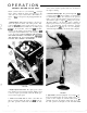
SlMPLIClTY O F F E R S OPERATION Easy to get on and off. Full length foot rest is convenient step. Controls are out~of the way. Comfortable foot support Large area foot rests permit changing foot position without resting feet on mower. Reduced noise and vibration, Enclosed, large vOlUme muffler lowers engine noise. Synchro-balanced engine (Sovereign) and massive frame (Sovereign and Landlord) minimizevibration. Quick, simple starting. High capacity battery. Key-controlled electric starter/generator.
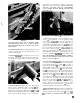
OPERATION CONTROLS AND HOW TO USE THEM Picture yourself seated on your Landlord or Sovereign tractor. ‘Before starting the engine, lets learn how to use each of the safe, easy to reach controls. (The numbers on figures 1 thru 7 correspond to the paragraph numbers below. ::. .:: ;,: ,.. 1. Ignition Switch: When turned clockwise to the first position, the ignition is turned “ON”. Turn past the “ON” position to actua@ the starter.
speed when the power take-off is engaged to absorb the initial effort of the added load. ALWAYS DISENGAGE THE P.T.O. AND WAIT UNTIL ALL ATTACHMENTS HAVE STOPPED MOVING BEFORE LEAVING THE TRACTOR SEAT. :.: .:, ;.:7 ..~.. .~:: FIGURE 5 FIGURE 3 ATE THE LIGHTS FOR OVER 10 MINUTES WHEN THE GENERATOR LIGHT IS ON OR THE BATTERY MAY DISCHARGE ENOUGH SO IT WILL NOT START THE ENGINE. 6. Fuel Gauge and Filler Cap: The gauge measures the level of fuel in the tank.
BRAKES WILL NOT FUNCTION IF THE GEAR SHIFT LEVER AT THE REAR OF THE TRACTOR IS IN THE The diagram printed on the panel shows the locatioi~ of each position. To shift the transmission into reverse or second, pull the shift lever back toward you, then push it all the way to the right or left into the desired position. To shift into first or third, push the shift lever forward and move it left or right all the way to the desired position.
sonally check each one so that you will become familiar with them and also to insure that your tractor is ready to go the first time you use it. 1. Tire Inflation: The tractor is shipped with all tires inflated to 25 PSI. Before operating, reduce pressure in all tires. The front tires 12 to 15 PSI and rear to 6 to 8 PSI. the hydrostatic pump. Oil should be level with the bottom edge of this hole. If it is not see page 17 under Maintenance. Remove the pipe plug from ~the elbow on the axle housing.
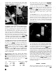
using + rotary mower with your tractor, the front to rear height adjustment must be checked. STARTING THE ENGINE 1. Insure that the power take-off is disengagtid by moving the lever to the rear and down. If your tractor has attachments mounted, be sure the power drives to them are disengaged. (See figure 14). .~.; ::: 1 :, :.: : FIGURE 14 2. Place the transmission shift lever or hydrostatic control in neutral. THE ENGINE WILL NOT START UNLESS THE TRANSMISSION LEVERS ARE IN NEUTRAL. (See figure 15).
lever to fast or slow as needed for the operation. DO NOT ALLOW THE ENGINE TO RUN IN AN ENCLOSED BUILDING WHERE CARBON MONOXIDE ,,MAY ACCUMULATE. STOPPING THE ENGINE 1. Move the speed control lever to the slow position. To gradualb reduce engine temperature allow the engine to idle for about a minute if the tractor has been pperated under full load. Stopping a hot engine too sudd’enly can cause damage to engine parts. FIGURE 16 4. Move the engine speed control lever forward about l/3 of the way.
3. Disengage the power-take-off clutch and lower any attachments to the ground. IF BELT SLIPPAGE OCCURS, check the following: 1. Belts may be stretched or excessively worn. 4. If the engine has been working under full load, allow the engine to idle about a minute before turning the ignition key counterclockwise to the off position. 5. Remove the key to prevent unauthorized use of the tractor. 2. Pulleys may be greasy or oily. ,: 3. Insufficient belt tension due to a broken or worn tension spring.
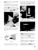
The Landlord and Sovereign tractors have been designed for easy accessability to areas which need to be reached in making adjustments and performing maintenance. The underside of the frame has been left open to provide easy access to areas requiring lubrication, adjustment or repairs. ,. :.. The tractor hood is hinged at the front by two spring loaded bolts. It may be easily opened by releasing the two rubber straps which are located one on each side at the rear of the hood.
starter will actuate. If difficulty is experienced in moving the shift lever through the neutral position, raise the switch until the shift lever moves easily. Place a film of grease on the end of the safety interlock to reduce friction and wear. VARIABLE SAFETY INTERLOCK ,FIGURE FIGURE 21 Power Take-Off Clutch and Belt Stops: The power take-off clutch can be correctly adjusted only when the attachment such as a mower or sickle bar is mounted and the drive belt connected.
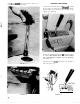
speed control lever is in the Neutral position, the turnbuckle may need adjusting. See figure 24. To adjust, place the control lever in the neutral position. THE HYDROSTATIC LOCKOUT AT THE REAR OF THE TRACTOR MUST BE IN THE “DRIVE” POSITION. Loosen the nuts at each end of the turnbuckle. Start the engine. If the tractor creeps forward turn the top of the turnbuckle toward the tractor. If the tractor creeps backward, rcztate the top of the turnbuckle away from the tractor.
. ,_’ VARIABLE SPEED BkAKE ADJUSTMENT FIGURE 26 Brake Adjustment, Parking: The parking brake is actuated and adjusted independentally of the foot brake. It is found at the rear of the left footrest on tractors with variable speed transmissions and the right footrest on tractors equipped with hydrostatic transmission. To adjust the parking brake, loosen the nut located behind the footrest. See figure 27:Rotate the brake lever clockwise to tighten and FIGURE 27 counterclockwise to loosen the brake.
MAINTENANCE .:’ ,~, Regular maintenance of your Simplicity tractor will greatly increase its useful life and reduce repair costs. A wide variety of attachments and accessories permit use of your tractor throughout the year. BECAUSE YOUR TRACTOR IS A MULTI-SEASON TOOL, IT IS VERY IMPORTANT TO SERVICE THE ENGINE FOR THE SEASON IN WHICH IT WILL BE OPERATED. Be sure to change to winter grade oil before making cold temperature starts. Fuel refiners change the volatility of gasoline for each season of the year.
FIGURE 34 FIGURE 31 4. Lubricate Grease Fittings: There are six grease zerks on 5. Check the Oil Level in the gear box located above the power take-off. Turn the pipe plug counterclockwise to ren~ove. The oil should be level with the top of the elbow at the rear of the gear box. If necessary, add SAE 90 wt. transmission oil. Reinstall the plug securely. See figure 35.
normally necessary. but if you wish to drain oil from the transmission; the drain plug is located at the lower right side of the transmission. FIGURE 37 FIGURE 38 (Hydrostatic Transmission): Check the oil level of the hydrostatic unit with the engine stopped dt the plug in the reservoir. (See figure IO.) Turn the plug counterclockwise to remove. The oil should be level with the bottom of the threads. If it is not.
just before charging to mix the solution. DO NOT OVER FILL THE BATTERY. FIGURE 41 9. Check the Air Pressure on Tires: Front 12-15 PSI and Rear 6-8 PSI. EVERY 100 HOURS OR ONCE A YEAR 1. Remove the Spark Plug. clean or replace and set the gap at ,030. DO NOT SAND BLAST PLUGS, AS THE ABRASIVE PARTICLES LEFT ON THE PLUG MAY DAMAGE THE ENGINE. Plugs may be cleaned by scraping or wire brushing and washing in a solvent. 2. Remove the Battery Cables.
be taken to insure your tractor will be, ready to go when you need it. 1. Drain the fuel tank completely by cunning the tractor until it stops. This may be easily done by removing the gas line at the carburetor, and draining the tank through this hose. If you desire, fuel may be stored in the tank or a shall container if a good brand of gasoline stabilizer is used.
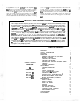
ENGINE SPECIFICATIONS MAKE SOVEREIGN I Briggs & Stratton 320421 MODEL NO. SHAFT I PLANE Horizontal HORSEPOWER (AT 3600 RPM) PISTON 243431 One (Cast Iron) NUMBER OF CYLINDERS CRANK L A N D L O R D _. ., 14 DISPLACEMENT 1. 10 32.4 Cu. In. BORE 3.9116” 3-l/4” STROKE 3.114” 3.114” CYLINDER Cast Iron MATERIAL EXHAUST VALVE AND SEAT I VALVE ROTATORS I SYNCHRO BALANCED (85% GOVERNOR Stellite Yes Horizontally, 60% Vertiaally) TYPE 1 .
HYDROSTATIC MAKE Vickers TYPE Piston to Piston LUBRICATION AND WORKING FLUID Type A Automatic Transmission SAPACITY ,: : : TRANSMISSION (INDEPENDENT SYSTEM) l-314 Quarts TEMPERATURE PROTECTION Oil Cooler with Fan and Cold Weather By-Pass Valve VEUTRAL z Pattern Control IDENTIFICATION DISCONNECT (PUSHING) Sliding Gear SLUTCH (STARTING and OPERATING) V-Belt Idler Drive SPEEDS O-7 MPH Forward, O-4 MPH Reverse (STEPLESS HOLDS POSITION) SOFT RIDE VALVE Fast Acting (No Spring Change Req
BEVEL GEAR HOUSING (Hydrostatic and Variable) Simplicity MAKE HOUSING MATERIAL I I I BEARINGS I LUBRICATION DIFFERENTIAL (Hydrostatic and Variable) HOUSING MATERIAL Bevel Type, Hardened Steel Rolling Contact SAE 90, Capacity 1 Quart I I Simplicity I Drawn Steel GEARS LIMITED Cast Iron Spur Type. Hardened Steel SLIP 8 Springs and Hardened Washers Automatically Transfer Maximum Driving Force From Slipping Wheel Which is Possible Without Scuffing Lawns On Turns. Clutch Is V-Belt Idler.
$OVERElGN LANDLORD 30” READ FRONT (Inside Tires) TREAD REAR (Inside Tires) TURNING 26” RADIUS 30.112” TIRES, FRONT,Size 16x6.50x8 4.8/4.0x 8 I TYPE AND INFLATION PRESSURE Pneumatic, 6-8 psi Rear, 12-15 psi Front TREAD Turf TIRES, REAR, Size NET WEIGHT SIDE HILL AND UPHILL OPERATION 23~10.50~12 23x8.
ACCESSaRIES MFG. .MFG. MFG. MFG. MFG. MFG. MFG. MFG. MFG. MFG. MFG. MFG., MFG. MFG. MFG. MFG. MFG. MFG. MFG. MFG. MFG. MFG. ., MFG. 24 NO. NO. NO. NO. NO. NO. NO. NO. NO. NO. NO. NO. NO. NO. NO. NO. NO. NO. NO. NO. NO. NO. 574 673 504 686 685 689 466 280 617 536 449 668 182 045 658 584 690 523 315 181 635 636 NO.