5/13/2010 1:02 PM Page 6-1 Power Power 6-Table of Contents Table of Contents Safety Distributed Starters Safety Drives Safety Drives and Motion Introduction 6-35 PowerFlex 40P ..............................................................................................6-38 PowerFlex 70 ................................................................................................6-41 PowerFlex 700H ............................................................................................
01_280_DistMotorCntl 5/13/2010 1:08 PM Page 6-2 Power Safety ArmorStart® Distributed Motor Controllers Bulletin 280D/281D 6-Distributed Motor Controllers 280D/281D ArmorStart Distributed Motor Controller — Safety Version Standards Compliance UL 508 CSA C22.2, No. 14 EN/IEC 60947-1 CCC CE Marked per Low Voltage Directive 73/23/EEC and EMC Directive 89/336/EEC Mode of Operation Full-Voltage Start This method is used in applications requiring across-the-line starting.
01_280_DistMotorCntl 5/13/2010 1:08 PM Page 6-3 Power Safety ArmorStart® Distributed Motor Controllers Bulletin 280D/281D 6-Distributed Motor Controllers Cat. No. Explanation Examples given in this section are for reference purposes. This basic explanation should not be used for product selection; not all combinations will produce a valid catalog number.
01_280_DistMotorCntl 5/13/2010 1:08 PM Page 6-4 Power Safety ArmorStart® Distributed Motor Controllers Bulletin 280D/281D 6-Distributed Motor Controllers Options – Factory Installed Description Cat. No.
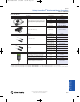
01_280_DistMotorCntl 5/13/2010 1:08 PM Page 6-5 Power Safety ArmorStart® Distributed Motor Controllers Bulletin 280D/281D Length [m (ft)] Cat. No. 1 (3.3) 1485P-P1E4-B1-N5 2 (6.5) 1485P-P1E4-B2-N5 3 (9.8) 1485P-P1E4-B3-N5 6 (19.8) 1485P-P1E4-B6-N5 Left Keyway 1485P-P1N5-MN5KM Right Keyway 1485P-P1N5-MN5NF Description Grey PVC Thin Cable Thick Cable Connector Cat. No.
01_280_DistMotorCntl 5/13/2010 1:08 PM Page 6-6 Power Safety ArmorStart® Distributed Motor Controllers Bulletin 280D/281D 6-Distributed Motor Controllers Sensor Media ArmorStart I/O Connection Description DC Micro Patchcord Principles DC Micro VCable AC Micro Patchcord Input Input Output Pin Count 5-pin 5-pin 3-pin Connector Cat. No.
01_280_DistMotorCntl 5/13/2010 1:09 PM Page 6-7 Power Safety ArmorStart® Distributed Motor Controllers Each ArmorStart Safety Distributed motor controller is intended to be combined with the 1732DS-IB8XOBV4 safety I/O module to form a subsystem that is part of the overall machine stop function. The motor controllers are connected to the safety I/O module through specified cable assemblies.
01_280_DistMotorCntl 5/13/2010 1:09 PM Page 6-8 Power Safety ArmorStart® Distributed Motor Controllers Bulletin 280D/281D 6-Distributed Motor Controllers ArmorBlock® Guard I/O™ Modules Description Cat. No. Principles ArmorBlock Guard I/O provides all the advantages of traditional distributed I/O for safety systems, but has an IP67 package that can be mounted directly on your machine.
01_280_DistMotorCntl 5/13/2010 1:09 PM Page 6-9 Power Safety ArmorStart® Distributed Motor Controllers 1732DS ArmorBlock Guard I/O Micro Connector Pin Assignments Input Configuration Output Configuration Pin Signal Female 1 Test Output n+1 2 Safe Input n+1 3 Input Common 4 Safe Input n 5 Test Output n 2 5 1 3 4 Pin Signal 1 Output +24V DC Power 2 Output n+1 (Sinking) 3 Output Power Common 4 Output n (Sourcing) 5 Output Power Common Principles 1732DS ArmorBlock Guard I/O
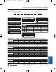
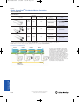
01_280_DistMotorCntl 5/13/2010 1:09 PM Page 6-10 Power Safety ArmorStart® Distributed Motor Controllers Bulletin 280D/281D 6-Distributed Motor Controllers Specifications Electrical Ratings Rated Operation Voltage UL/NEMA IEC 380Y/220…480Y/277V AC 380Y/220…480Y/277V AC Rate Insulation Voltage 600V Rated Impulsed Voltage 4 kV Dielectric Withstand 2200V AC 2500V AC Operating Frequency Power Circuit 50/60 Hz Utilization Category — Protection Against Shock — AC-3 IP2X 2.
01_280_DistMotorCntl 5/13/2010 1:09 PM Page 6-11 Power Safety ArmorStart® Distributed Motor Controllers Bulletin 280D/281D Environmental IEC -20…+40 °C (-4…+104 °F) Storage and Transportation Temperature Range –25….+85 °C (–13…+185 °F) Altitude 2000 m Humidity 5…95% (non-condensing) Pollution Degree Enclosure Ratings 6-Distributed Motor Controllers UL/NEMA Operating Temperature Range 3 NEMA 4/12/13 IP67 Approximate Shipping Weight 6.
01_280_DistMotorCntl 5/13/2010 1:09 PM Page 6-12 Power Safety ArmorStart® Distributed Motor Controllers Bulletin 280D/281D 6-Distributed Motor Controllers External Connections for Input Connector Safety Monitor Input (SM1/SM2) Pin 1: +V Out Pin 2: Input Pin 3: Comm Pin 4: Input Pin 5: NC (No Connection) Pin 1: SM2 - White Pin 2: SM1 - Brown Pin 3: NC (No Connection) Pin 4: NC (No Connection) External Connections for Output Connector Principles External Connections for Safety Input Power (A1/A2)
01_280_DistMotorCntl 5/13/2010 1:09 PM Page 6-13 Power Safety ArmorStart® Distributed Motor Controllers Bulletin 280D/281D 6-Distributed Motor Controllers Overload Curves Approximate Trip Time [s] Class 10 Principles Cold Hot % Full Load Current Approximate Trip Time [s] 9- Class 15 10-Safety Applications Cold Hot % Full Load Current 11-Cat. No. Index Approximate Trip Time [s] Class 20 Logic Cold Hot 6-Distributed Motor Controllers % Full Load Current Visit our website: www.ab.
01_280_DistMotorCntl 5/13/2010 1:09 PM Page 6-14 Power Safety ArmorStart® Distributed Motor Controllers Bulletin 280D/281D 6-Distributed Motor Controllers Approximate Dimensions Dimensions for IP67/NEMA Type 4 with Conduit Entrance Dimensions in millimeters (inches). Dimensions are not intended to be used for manufacturing purposes. All dimensions are subject to change. Principles 9- 10-Safety Applications 11-Cat. No. Index Logic 6-Distributed Motor Controllers Visit our website: www.ab.
01_280_DistMotorCntl 5/13/2010 1:09 PM Page 6-15 Power Safety ArmorStart® Distributed Motor Controllers Bulletin 280D/281D 6-Distributed Motor Controllers Dimensions for IP67/NEMA Type 4 with ArmorConnect Connectivity 6-Distributed Motor Controllers Logic 11-Cat. No. Index 10-Safety Applications 9- Principles Dimensions in millimeters (inches). Dimensions are not intended to be used for manufacturing purposes. All dimensions are subject to change. Visit our website: www.ab.
01_280_DistMotorCntl 5/13/2010 1:09 PM Page 6-16 Power Safety ArmorStart® Distributed Motor Controllers Bulletin 280D/281D 6-Distributed Motor Controllers Dimensions for Reversing, IP67/NEMA Type 4 with Conduit Entrance Dimensions in millimeters (inches). Dimensions are not intended to be used for manufacturing purposes. All dimensions are subject to change. Principles 9- 10-Safety Applications 11-Cat. No. Index Logic 6-Distributed Motor Controllers Visit our website: www.ab.
01_280_DistMotorCntl 5/13/2010 1:09 PM Page 6-17 Power Safety ArmorStart® Distributed Motor Controllers Bulletin 280D/281D 6-Distributed Motor Controllers Dimensions for Reversing, IP67/NEMA Type 4 with ArmorConnect Connectivity 6-Distributed Motor Controllers Logic 11-Cat. No. Index 10-Safety Applications 9- Principles Dimensions in millimeters (inches). Dimensions are not intended to be used for manufacturing purposes. All dimensions are subject to change. Visit our website: www.ab.
01_280_DistMotorCntl 5/13/2010 1:09 PM Page 6-18 Power Safety ArmorStart® Distributed Motor Controllers Bulletin 284D 6-Distributed Motor Controllers Bulletin 284D ArmorStart Distributed Motor Controller Safety Version Description Principles 9- The Bulletin 284 ArmorStart Distributed Motor Controller is an integrated, pre-engineered starter for variable frequency AC drive applications.
01_280_DistMotorCntl 5/13/2010 1:09 PM Page 6-19 Power Safety ArmorStart® Distributed Motor Controllers Description of Features Overload Protection Factory Installed Options HOA Selector Keypad with Jog Function The Bulletin 284 ArmorStart Distributed Motor Controller incorporates, as standard, electronic motor overload protection. This overload protection is accomplished electronically with an I2t algorithm.
01_280_DistMotorCntl 5/13/2010 1:09 PM Page 6-20 Power Safety ArmorStart® Distributed Motor Controllers Bulletin 284D 6-Distributed Motor Controllers Cat. No. Explanation Examples given in this section are for reference purposes. This basic explanation should not be used for product selection; not all combinations will produce a valid catalog number.
01_280_DistMotorCntl 5/13/2010 1:09 PM Page 6-21 Power Safety ArmorStart® Distributed Motor Controllers Bulletin 284D Description Cat. No.
01_280_DistMotorCntl 5/13/2010 1:09 PM Page 6-22 Power Safety ArmorStart® Distributed Motor Controllers Bulletin 284D 6-Distributed Motor Controllers DeviceNet Media ♣ Description Length [m (ft)] Cat. No. 1 (3.3) 1485P-P1E4-B1-N5 2 (6.5) 1485P-P1E4-B2-N5 3 (9.8) 1485P-P1E4-B3-N5 6 (19.
01_280_DistMotorCntl 5/13/2010 1:09 PM Page 6-23 Power Safety ArmorStart® Distributed Motor Controllers Zone 3 Zone 2 Zone 1 The Zone Control capabilities of ArmorStart Distributed Motor Controller is ideal for large horsepower (0.5…10 Hp) motored conveyors.
01_280_DistMotorCntl 5/13/2010 1:09 PM Page 6-24 Power Safety ArmorStart® Distributed Motor Controllers Bulletin 284D 6-Distributed Motor Controllers Safety I/O Module and TÜV Requirements ArmorStart Safety-Related Parts Each ArmorStart Safety Distributed motor controller is intended to be combined with the 1732DS-IB8XOBV4 safety I/O module to form a subsystem that is part of the overall machine stop function.
01_280_DistMotorCntl 5/13/2010 1:09 PM Page 6-25 Power Safety ArmorStart® Distributed Motor Controllers ArmorBlock® Guard I/O™ Modules Cat. No. 1732DS-IB8XOBV4 Principles Description ArmorBlock Guard I/O provides all the advantages of traditional distributed I/O for safety systems, but has an IP67 package that can be mounted directly on your machine.
01_280_DistMotorCntl 5/13/2010 1:09 PM Page 6-26 Power Safety ArmorStart® Distributed Motor Controllers Bulletin 284D 6-Distributed Motor Controllers 1732DS ArmorBlock Guard I/O Micro Connector Pin Assignments Input Configuration Output Configuration Pin Signal Female 1 Test Output n+1 2 Safe Input n+1 3 Input Common 4 Safe Input n 5 Test Output n 2 5 1 3 4 Pin Signal 1 Output +24V DC Power 2 Output n+1 (Sinking) 3 Output Power Common 4 Output n (Sourcing) 5 Output Power
01_280_DistMotorCntl 5/13/2010 1:09 PM Page 6-27 Power Safety ArmorStart® Distributed Motor Controllers Bulletin 284D Electrical Ratings Power Circuit UL/NEMA IEC Rated Operation Voltage 200…575V 200…500V 600V Rate Insulation Voltage 600V Rated Impulsed Voltage 6 kV 6 kV Dielectric Withstand 2200V AC 2500V AC Operating Frequency 50/60 Hz 50/60 Hz Utilization Category N/A AC-3 Protection Against Shock N/A IP2X 6-Distributed Motor Controllers Specifications 24V DC (+10%, -15%)
01_280_DistMotorCntl 5/13/2010 1:09 PM Page 6-28 Power Safety ArmorStart® Distributed Motor Controllers Bulletin 284D 6-Distributed Motor Controllers UL/NEMA Environmental IEC Operating Temperature Range -20…+40 °C (-4…+104 °F) Storage and Transportation Temperature Range –25….+85 °C (–13…+185 °F) Altitude 1000 m Humidity 5…95% (non-condensing) Pollution Degree Enclosure Ratings 3 NEMA 4/12/13 IP67 NEMA 4X IP69K Approximate Shipping Weight 13.
01_280_DistMotorCntl 5/13/2010 1:09 PM Page 6-29 Power Safety ArmorStart® Distributed Motor Controllers Bulletin 284D External Connections for Dynamic Brake Connection Pin 1: +V Out Pin 2: Input Pin 3: Comm Pin 4: Input Pin 5: NC (No Connection) 6-Distributed Motor Controllers External Connections for Input Connector Pin 1: GND - Green/Yellow Pin 2: BR+ - Black Pin 3: BR- - White External Connections for Output Connector External Connections for 0…10V Analog Input External Connections for Device
01_280_DistMotorCntl 5/13/2010 1:09 PM Page 6-30 Power Safety ArmorStart® Distributed Motor Controllers Bulletin 284D 6-Distributed Motor Controllers Dimensions for Safety Product, 2 Hp and below @ 460V AC, IP67/NEMA Type 4 with Conduit Entrance Dimensions in millimeters (inches). Dimensions are not intended to be used for manufacturing purposes. All dimensions are subject to change. Principles 9- 10-Safety Applications 11-Cat. No. Index Logic 6-Distributed Motor Controllers Visit our website: www.
01_280_DistMotorCntl 5/13/2010 1:09 PM Page 6-31 Power Safety ArmorStart® Distributed Motor Controllers Bulletin 284D 6-Distributed Motor Controllers Dimensions for Safety Product, 2 Hp and below @ 460V AC, NEMA Type 4 with ArmorConnect™ Connectivity 6-Distributed Motor Controllers Logic 11-Cat. No. Index 10-Safety Applications 9- Principles Dimensions in millimeters (inches). Dimensions are not intended to be used for manufacturing purposes. All dimensions are subject to change.
01_280_DistMotorCntl 5/13/2010 1:09 PM Page 6-32 Power Safety ArmorStart® Distributed Motor Controllers Bulletin 284D 6-Distributed Motor Controllers Dimensions for Safety Product, 3 Hp and above @ 460V AC, IP67/NEMA Type 4 with Conduit Entrance Dimensions in millimeters (inches). Dimensions are not intended to be used for manufacturing purposes. All dimensions are subject to change. Principles 9- 10-Safety Applications 11-Cat. No. Index Logic 6-Distributed Motor Controllers Visit our website: www.
01_280_DistMotorCntl 5/13/2010 1:09 PM Page 6-33 Power Safety ArmorStart® Distributed Motor Controllers Bulletin 284D 6-Distributed Motor Controllers Dimensions for Safety Product, 3 Hp and above @ 460V AC, IP67/NEMA Type 4 with ArmorConnect Connectivity 6-Distributed Motor Controllers Logic 11-Cat. No. Index 10-Safety Applications 9- Principles Dimensions in millimeters (inches). Dimensions are not intended to be used for manufacturing purposes. All dimensions are subject to change.
01_280_DistMotorCntl 5/13/2010 1:09 PM Page 6-34 Power Safety ArmorStart® Distributed Motor Controllers Bulletin 284D 6-Distributed Motor Controllers Dynamic Brake Resistors Dimensions are in millimeters. Dimensions are not intended to be used for manufacturing purposes. A H Principles B C D J E F G 9Cat. No. A 284R-091P500 284R-360P500 284R-120P1K2 B C D 215±5 75±3 215±5 E F G H J 60±2 127 12.54 60±2 50±1.
s117_drives_04162010 5/13/2010 1:15 PM Page 6-35 Power Safety Solutions for PowerFlex Drives ® Introduction Help improve machine uptime and reduce wear and tear with safety-rated PowerFlex and Kinetix drives In addition to the safe monitoring of speed dependent functions, the Safe Speed Monitor integrates the functionality of a safety monitoring relay, providing direct inputs for interfacing door locks, light curtains, E-Stop pushbuttons, enabling switches, and key switches.
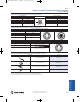
s117_drives_04162010 5/13/2010 1:16 PM Page 6-36 Power Safety Solutions for PowerFlex® Drives Overview 6-Safety Drives The Allen-Bradley PowerFlex 40P, 70, 700H, 700L, 700S, 753 and 755 offer certified safety options to help provide integral, costeffective, and certified protection for AC drive control. All safety options are available as a kit for user installation. Principles PowerFlex 40P PowerFlex 70 PowerFlex 700H 200…240V Ratings 0.37…7.5 kW (0.
s117_drives_04162010 5/13/2010 1:16 PM Page 6-37 Power Safety Solutions for PowerFlex Drives ® Principles PowerFlex 755 9- PowerFlex 753 0.75…66 kW (1…100 Hp) – – – 0.75…800 kW (1…1250 Hp) ‡ 200…860 kW (300…1150 Hp) 0.75…250 kW (1…350 Hp) 0.75…250 kW (1…350 Hp) 0.
s117_drives_04162010 5/13/2010 1:16 PM Page 6-38 Power Safety Solutions for PowerFlex® Drives PowerFlex 40P AC Drive 6-Safety Drives 200…240V: 0.37…7.5 kW / 0.5…10 Hp / 2.3…33 A Ratings 380…480V: 0.37…11 kW / 0.5…15 Hp / 1.4…24 A 500…600V: 0.75…11 kW / 1…15 Hp / 1.7…19 A Principles 9- The PowerFlex 40P AC drive addresses user needs for closed loop control with an option for Category 3 Safe Torque-off in a compact and cost effective design.
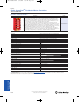
s117_drives_04162010 5/13/2010 1:16 PM Page 6-39 Power Safety Solutions for PowerFlex Drives ® PowerFlex 40P AC Drive IP20/NEMA Type Open IP20 Plate Drive IP20 Flange Mount 1 Cat. No. Cat. No. Cat. No. Output Current kW Hp A Frame Size 0.75 1 1.7 B 22D-E1P7N104 22D-E1P7H204 22D-E1P7F104 1.5 2 3 B 22D-E3P0N104 22D-E3P0H204 22D-E3P0F104 2.2 3 4.2 B 22D-E4P2N104 22D-E4P2H204 22D-E4P2F104 4 5 6.6 B 22D-E6P6N004 22D-E6P6H204 22D-E6P6F104 5.5 7.5 9.
s117_drives_04162010 5/13/2010 1:16 PM Page 6-40 Power Safety Solutions for PowerFlex® Drives PowerFlex 40P AC Drive Safety Options IP30, NEMA/UL Type 1 Conversion Kit 6-Safety Drives Description DriveGuard Safe Torque-Off Cat. No. Description Frame Cat. No. 20A-DG01 Converts IP20 drive to IP30, NEMA/UL Type 1 enclosure. Includes conduit box, mounting screws and plastic top panel. B 22-JBAB C 22-JBAC B 22-JBCB C 22-JBCC Terminators Description 1 Cat. No. for use with 3.
s117_drives_04162010 5/13/2010 1:16 PM Page 6-41 Power Safety Solutions for PowerFlex Drives ® 500…600V: 0.37…37 kW / 0.5…50 Hp / 0.9…52 A Motor Control V/Hz control Sensorless Vector Control Flux Vector Control Communications Common Industrial Protocol User Interface HIM (option) Enclosures IP20, Flange Mount, IP66 / NEMA 4X Safety DriveGuard Safe Torque-Off / EN 954-1 Cat.
s117_drives_04162010 5/13/2010 1:16 PM Page 6-42 Power Safety Solutions for PowerFlex® Drives PowerFlex 70 AC Drive Panel Mount - IP 20, NEMA/UL Type 1, No HIM (continued) 6-Safety Drives 380...480V AC, Three-Phase Drives 480V AC Input Output Amps Cont. 1 Min. 3 Sec. Normal Duty Hp 400V AC Input Heavy Duty Hp Cat. No. Output Amps Cont. 1 Min. 3 Sec. Normal Duty kW Heavy Duty kW Cat. No. with Filter Frame Size Principles 9- 1.1 1.2 1.6 0.5 0.33 20AD1P1A0AYNNNC0 1.3 1.4 1.9 0.
s117_drives_04162010 5/13/2010 1:16 PM Page 6-43 Power Safety Solutions for PowerFlex Drives ® PowerFlex 70 AC Drive 208V AC Input 240V AC Input Output Amps Output Amps Heavy Duty Hp Cat. No. Normal Duty kW Heavy Duty kW Cat. No. with Filter Cont. 1 Min. 3 Sec. Normal Duty Hp 2.2 2.4 3.3 0.5 0.33 20AB2P2C3AYNNNC0 2.5 2.7 3.7 0.37 0.25 20AB2P2C3AYNNNC0 N B 2.2 2.4 3.3 0.5 0.33 20AB2P2C3AYNANC0 2.5 2.7 3.7 0.37 0.25 20AB2P2C3AYNANC0 Y B 4.2 4.8 6.4 1 0.
s117_drives_04162010 5/13/2010 1:16 PM Page 6-44 Power Safety Solutions for PowerFlex® Drives PowerFlex 70 AC Drive Wall / Machine Mount - IP66, NEMA/UL Type 4X/12, with HIM, For Indoor Use (continued) 6-Safety Drives 500...600V AC, Three-Phase Drives 600V AC Input Output Amps 1 Min. 3 Sec. Normal Duty Hp Heavy Duty Hp Cat. No. with Filter Frame Size 0.9 1 1.4 0.5 0.33 20AE0P9C3AYNNNC0 N B 1.7 1.9 2.6 1 0.75 20AE1P7C3AYNNNC0 N B 2.7 3.6 4.8 2 1 20AE2P7C3AYNNNC0 N B 3.
s117_drives_04162010 5/13/2010 1:16 PM Page 6-45 Power Safety Solutions for PowerFlex Drives ® PowerFlex 70 AC Drive 208V AC Input 240V AC Input Output Amps Cat. No. with Filter Cont. 1 Min. 3 Sec. 2.2 2.4 3.3 0.5 0.33 20AB2P2F0AYNNNC0 2.5 2.7 3.7 0.37 0.25 20AB2P2F0AYNNNC0 N A 2.2 2.4 3.3 0.5 0.33 20AB2P2F0AYNANC0 2.5 2.7 3.7 0.37 0.25 20AB2P2F0AYNANC0 Y B 4.2 4.8 6.4 1 0.75 20AB4P2F0AYNNNC0 4.8 5.5 7.4 0.75 0.55 20AB4P2F0AYNNNC0 N A 4.2 4.8 6.
s117_drives_04162010 5/13/2010 1:16 PM Page 6-46 Power Safety Solutions for PowerFlex® Drives PowerFlex 70 AC Drive Flange Mount - Front Chassis = IP20, NEMA/UL Type 1, Heatsink = IP66, NEMA/UL Type 4X/12, No HIM (continued) 6-Safety Drives 500...600V AC, Three-Phase Drives 600V AC Input Output Amps 1 Min. 3 Sec. Normal Duty Hp Heavy Duty Hp Cat. No. with Filter Frame Size 0.9 1 1.4 0.5 0.33 20AE0P9F0AYNNNC0 N A 1.7 1.9 2.6 1 0.75 20AE1P7F0AYNNNC0 N A 2.7 3.6 4.
s117_drives_04162010 5/13/2010 1:16 PM Page 6-47 Power Safety Solutions for PowerFlex Drives ® 500…600V: 160…2000 kW / 250…900 Hp / 261…820 A 690V: 160…2300 kW / 150…2400 Hp / 170…2250 A Motor Control V/Hz control Sensorless Vector Control Communications Common Industrial Protocol User Interface HIM (option) Enclosures IP21 Safety DriveGuard Safe Torque-Off / EN954-1 Cat.
s117_drives_04162010 5/13/2010 1:16 PM Page 6-48 Power Safety Solutions for PowerFlex® Drives PowerFlex 700H AC Drive IP21, NEMA Type 1 (continued) 6-Safety Drives 600…690V AC, Three-Phase Drives with 24V DC I/O 600V AC Input 690V AC Input Output Amps 1 Cont. 1 Min. Normal Heavy Duty Duty 2 Sec. Hp Hp Output Amps 1 Cat. No. §® Cont. 1 Min. Normal Heavy Duty Duty 2 Sec. kW kW Cat. No.
s117_drives_04162010 5/13/2010 1:16 PM Page 6-49 Power Safety Solutions for PowerFlex Drives ® PowerFlex 700H AC Drive 480V AC Input 400V AC Input Output Amps 1 Cont. 1 Min. Normal Heavy Duty Duty 2 Sec. Hp Hp Output Amps 1 Cat. No. ® Cont. 1 Min. Normal Heavy Duty Duty 2 Sec. kW kW Cat. No.
s117_drives_04162010 5/13/2010 1:16 PM Page 6-50 Power Safety Solutions for PowerFlex® Drives PowerFlex 700H AC Drive IP54, NEMA Type 12, Rittal 6-Safety Drives 380…480V AC, Three-Phase Drives with 24V DC I/O 480V AC Input 400V AC Input Output Amps 1 Cont. 1 Min. Normal Heavy Duty Duty 2 Sec. Hp Hp Output Amps 1 Cat. No. ® Cont. 1 Min. Normal Heavy Duty Duty 2 Sec. kW kW Cat. No.
s117_drives_04162010 5/13/2010 1:16 PM Page 6-51 Power Safety Solutions for PowerFlex Drives ® 200…240V: 0.75…66 kW / 1…100 Hp / 4.2…260 A 380…480V: 0.75…800 kW / 1…1250 Hp / 2.1…1450 A Ratings 500…600V: 0.75…1500 kW / 1…1600 Hp / 1.7…1500 A 690V: Communications Common Industrial Protocol User Interface HIM (option) Enclosures IP20, IP21 Safety DriveGuard Safe Torque-Off / EN 954-1 Cat.
s117_drives_04162010 5/13/2010 1:16 PM Page 6-52 Power Safety Solutions for PowerFlex® Drives PowerFlex 700S AC Drive 380…480V AC, Three-Phase Drives 6-Safety Drives 480V AC Input Output Amps Normal Heavy Duty Duty Hp Hp 400V AC Input Output Amps Normal Heavy Duty Duty kW kW Principles Cat. No. Frame Size 0.55 20DC2P1A0EYNANANE 1 0.75 20DC3P5A0EYNANANE 1 2.2 1.5 20DC5P0A0EYNANANE 1 13.2 4 2.2 20DC8P7A0EYNANANE 1 13 17.4 5.5 4 20DC011A0EYNANANE 1 15.4 17.2 23.1 7.5 5.
s117_drives_04162010 5/13/2010 1:16 PM Page 6-53 Power Safety Solutions for PowerFlex Drives ® PowerFlex 700S AC Drive 1 Min. 3 Sec. Cat. No. Frame Size 1.7 2 2.6 1 0.5 20DE1P7A0EYNANANE – – – – – – 1 2.7 3.6 4.8 2 1 20DE2P7A0EYNANANE – – – – – – 1 3.9 4.3 5.9 3 2 20DE3P9A0EYNANANE – – – – – – 1 6.1 6.7 9.2 5 3 20DE6P1A0EYNANANE – – – – – – 1 9 9.9 13.5 7.5 5 20DE9P0A0EYNANANE – – – – – – 1 11 13.5 18 10 7.
s117_drives_04162010 5/13/2010 1:16 PM Page 6-54 Power Safety Solutions for PowerFlex® Drives PowerFlex 700S AC Drive IP21, NEMA/UL Type 1, MCC 6-Safety Drives 380…480V AC, Three-Phase Drives 480V AC Input Output Amps Cont. 1 Min. Normal Heavy Duty Duty Hp Hp 3 Sec. 400V AC Input Output Amps Cat. No. Cont. 1 Min. 3 Sec. Normal Heavy Duty Duty kW kW Cat. No.
s117_drives_04162010 5/13/2010 1:16 PM Page 6-55 Power Safety Solutions for PowerFlex Drives ® 500…600V: 345…650 kW / 465…870 Hp / 425…800 A Motor Control Select PowerFlex 700 or PowerFlex 700S Control Communications Common Industrial Protocol 690V: 355…657 kW / 475…881 Hp / 380…705 A User Interface HIM (option) Enclosures IP00, IP20 Safety DriveGuard Safe Torque-Off / EN 954-1 Cat.
s117_drives_04162010 5/13/2010 1:16 PM Page 6-56 Power Safety Solutions for PowerFlex® Drives PowerFlex 700L AC Drive 600V AC, Three-Phase Drives 6-Safety Drives Output Amps Nominal Power Ratings 600V AC Input Cont. 1 Min. Normal Duty IP20, NEMA/UL Type 1 Heavy Duty 3 Sec. kW Hp kW Hp Cat. No.
s117_drives_04162010 5/13/2010 1:16 PM Page 6-57 Power Safety Solutions for PowerFlex Drives ® Motor Control Communications Common Industrial Protocol User Interface HIM (option) Enclosures IP00/IP20, Flange Mount, IP54/NEMA/UL Type 12 Safety Safe Torque-Off / EN 954-1 Cat. 3 Safe Speed Monitor PLe/SIL3 Cat.
s117_drives_04162010 5/13/2010 1:16 PM Page 6-58 Power Safety Solutions for PowerFlex® Drives PowerFlex 753 AC Drive 6-Safety Drives IP00/IP20, NEMA/UL Type Open 380…480V AC, Three-Phase Drives 480V AC Input Output Amps ‡ Normal Heavy Duty Duty Hp Hp 400V AC Input Output Amps ‡ Normal Heavy Duty Duty kW kW Principles 9- 10-Safety Applications 11-Cat. No. Index Cat. No. 1 Frame Size 0.75 20F11NC2P1JA0NNNNN 2 1.5 20F11NC3P5JA0NNNNN 2 2.2 2.2 20F11NC5P0JA0NNNNN 2 15.
s117_drives_04162010 5/13/2010 1:16 PM Page 6-59 Power Safety Solutions for PowerFlex Drives ® PowerFlex 753 AC Drive 3 Sec. Cat. No. Cont. 1 Min. 3 Sec. Normal Heavy Duty Duty kW kW Cat. No. Frame Size 2.1 3.1 3.7 1 1 20F11GD2P1AA0NNNNN 2.1 3.1 3.7 0.75 0.75 20F11GC2P11A0NNNNN 2 3.4 5.1 6.1 2 2 20F11GD3P4AA0NNNNN 3.5 5.2 6.3 1.5 1.5 20F11GC3P51A0NNNNN 2 5 7.5 9 3 3 20F11GD5P0AA0NNNNN 5 7.5 9.0 2.2 2.2 20F11GC5P01A0NNNNN 2 8 12 14.
s117_drives_04162010 5/13/2010 1:16 PM Page 6-60 Power Safety Solutions for PowerFlex® Drives PowerFlex 753 AC Drive 6-Safety Drives Flange Mount Front = IP20, NEMA/UL Type Open, Back/Heatsink = IP66, NEMA/UL Type 4X 380…480V AC, Three-Phase Drives 480V AC Input Output Amps ‡ Cont. 1 Min. 3 Sec. Normal Heavy Duty Duty Hp Hp 400V AC Input Output Amps ‡ Cat. No. Cont. 1 Min. 3 Sec. Normal Heavy Duty Duty kW kW Cat. No. Frame Size Principles 9- 2.1 3.1 3.7 1 1 20F11FD2P1AA0NNNNN 2.
s117_drives_04162010 5/13/2010 1:16 PM Page 6-61 Power Safety Solutions for PowerFlex Drives ® Motor Control Communications Embedded EtherNet/IP port standard, Common Industrial Protocol User Interface HIM (option) Enclosures IP00/IP20, Flange Mount, IP54/NEMA/UL Type 12 Safety Safe Torque-Off PLe/SIL3 Cat. 3 Safe Speed Monitor PLe/SIL3 Cat.
s117_drives_04162010 5/13/2010 1:16 PM Page 6-62 Power Safety Solutions for PowerFlex® Drives PowerFlex 755 AC Drive 6-Safety Drives IP00/IP20, NEMA/UL Type Open 380…480V AC, Three-Phase Drives 480V AC Input Output Amps ‡ Normal Heavy Duty Duty Hp Hp 400V AC Input Output Amps ‡ Normal Heavy Duty Duty kW kW Principles 9- 10-Safety Applications 11-Cat. No. Index Cat. No. 1 Frame Size 0.75 20G11NC2P11A0NNNNN 2§ 1.5 20G11NC3P51A0NNNNN 2§ 2.2 2.2 20G11NC5P01A0NNNNN 2§ 15.
s117_drives_04162010 5/13/2010 1:16 PM Page 6-63 Power Safety Solutions for PowerFlex Drives ® PowerFlex 755 AC Drive 3 Sec. Cat. No. Cont. 1 Min. 3 Sec. Normal Heavy Duty Duty kW kW Cat. No. 1 Frame Size 2.1 3.1 3.7 1 1 20G11GD2P1AA0NNNNN 2.1 3.1 3.7 0.75 0.75 20G11GC2P11A0NNNNN 2§ 3.4 5.1 6.1 2 2 20G11GD3P4AA0NNNNN 3.5 5.2 6.3 1.5 1.5 20G11GC3P51A0NNNNN 2§ 5 7.5 9 3 3 20G11GD5P0AA0NNNNN 5 7.5 9.0 2.2 2.2 20G11GC5P01A0NNNNN 2§ 8 12 14.
s117_drives_04162010 5/13/2010 1:16 PM Page 6-64 Power Safety Solutions for PowerFlex® Drives PowerFlex 755 AC Drive 6-Safety Drives Flange Mount Front = IP20, NEMA/UL Type Open, Back/Heatsink = IP66, NEMA/UL Type 4X 380…480V AC, Three-Phase Drives 480V AC Input Output Amps ‡ Normal Heavy Duty Duty Hp Hp Principles Cont. 1 Min. 3 Sec. 2.1 3.1 3.7 1 3.4 5.1 6.1 2 5 7.5 9 8 12 11 400V AC Input Output Amps ‡ Normal Heavy Duty Duty kW kW 9- Cat. No. 1 Frame Size 0.
s117_drives_04162010 5/13/2010 1:16 PM Page 6-65 Power Safety Solutions for PowerFlex Drives ® PowerFlex 7-Class Options 6-Safety Drives Human Interface and Wireless Interface Modules 20-HIM-A5 20-HIM-A6 20-HIM-C3S 20-HIM-C5S 20-HIM-C6S 20-WIM-N1 20-WIM-N4S Human Interface and Wireless Interface Modules Used with PowerFlex Drive Description Cat. No.
s117_drives_04162010 5/13/2010 1:16 PM Page 6-66 Power Safety Solutions for PowerFlex® Drives PowerFlex 7-Class Options Communication Option Kits 6-Safety Drives Used with PowerFlex Drive Description Cat. No.
s117_drives_04162010 5/13/2010 1:16 PM Page 6-67 Power Safety Solutions for PowerFlex Drives ® PowerFlex 7-Class Options Most legacy communication adapters (20-COMM) can be used with the PowerFlex 755. However, the restrictions stated below do apply. Accesses Ports 1…6 for I/O Accesses Port 7…14 Devices 20-COMM-B Supports Drive Add On Profiles Supports Asian-Languages ® Not Compatible v3.001 § 20-COMM-C 20-COMM-D ♣ v2.005 § v4.001 § 20-COMM-E v3.001 § Not Compatible ♣ v4.
s117_drives_04162010 5/13/2010 1:16 PM Page 6-68 Power Safety Solutions for PowerFlex® Drives PowerFlex 7-Class Options PowerFlex 750-Series Option Kits 6-Safety Drives Used with PowerFlex Drive Description Frame Cat. No.
s117_drives_04162010 5/13/2010 1:16 PM Page 6-69 Power Safety Solutions for PowerFlex Drives ® PowerFlex 7-Class Options Used with PowerFlex Drive Cat. No.
s117_drives_04162010 5/13/2010 1:16 PM Page 6-70 Power Safety Solutions for PowerFlex® Drives PowerFlex 7-Class Options PowerFlex 70 Small Duty Internal Dynamic Brake Resistors 6-Safety Drives Limited duty resistors mount directly to the back surface of the drive and require no extra panel space. Internal resistors are non-destructive and do not require a resistor overheat external safety circuit.
s117_drives_04162010 5/13/2010 1:16 PM Page 6-71 Power Safety Solutions for PowerFlex Drives ® PowerFlex 7-Class Options PowerFlex 70 AC Drive Medium Duty External DB Resistor Normal Duty1 [kW (Hp)] Heavy Duty1 [kW (Hp)] Min DB Res [Ohms ±10%] Resistance Continuous Max [Ohms Power Energy ±5%] [kW] [kJ] Cat. No. 0.37 (0.5) 0.25 (0.33) 33 AK-R2-091P500 91 0.086 17 0.75 (1.0) 0.55 (0.75) 33 AK-R2-091P500 91 0.086 17 1.5 (2.0) 1.1 (1.5) 33 AK-R2-091P500 91 0.086 2.2 (3.0) 1.
s117_drives_04162010 5/13/2010 1:16 PM Page 6-72 Power Safety Solutions for PowerFlex® Drives PowerFlex 7-Class Options Internal Dynamic Brake Resistor Kits 6-Safety Drives These resistors have a limited duty cycle. Refer to the PowerFlex Dynamic Braking Selection Guide to determine if an internal resistor will be sufficient for your application. An external resistor may be required. Used with PowerFlex Drive Drive Input Voltage Brake Resistance [Ω] Frame Cat. No.
s117_drives_04162010 5/13/2010 1:16 PM Page 6-73 Power Safety Solutions for PowerFlex Drives ® PowerFlex 7-Class Options Cat. No. 70 4 5 1321-RWR8-DP 700H 700S 700L 753/755 5.5 7.5 1321-RWR12-DP 7.5 10 1321-RWR18-DP 11 15 1321-RWR25-DP 15 20 1321-RWR35-DP 18.
s117_drives_04162010 5/13/2010 1:16 PM Page 6-74 Power Safety Solutions for PowerFlex® Drives 1492 Wiring System Modules and Cables 6-Safety Drives Wiring System Modules and Cables provide an easy means to extend drive control wiring. A pre-wired cable (available in various lengths) plugs into the appropriate drive I/O terminal block. The remaining cable end plugs into the Wiring Module which provides a terminal block for direct I/O connection. See publication 1492-TD008 for detailed information.
s117_kinetix_04162010 5/13/2010 1:19 PM Page 6-75 Power Safety Solutions for Kinetix Servo Drives ® Servo Drive Comparison Kinetix® Integrated Motion systems help increase machine productivity with GuardMotion™ technology. GuardMotion is the basis for safety innovations integrated into Kinetix motion products. Safe-off, also known as Safe Torque-off, helps machine builders and manufacturers implement machine solutions that provide safety and maximum availability.
s117_kinetix_04162010 5/13/2010 1:19 PM Page 6-76 Power Safety Solutions for Kinetix® Servo Drives Kinetix 300 Drives 6-Safety Motion Features PLd, Category 3 per ISO 13849-1 Stop Category 0 per EN 60204-1 Removable terminals Common solution for any power range Kinetix 300 Specifications Principles 9Description Kinetix® 10-Safety Applications 300 EtherNet/IP Indexing servo drives help protect personnel and increase machine productivity with Safe Torque-off functionality.
s117_kinetix_04162010 5/13/2010 1:20 PM Page 6-77 Power Safety Solutions for Kinetix Servo Drives ® Kinetix 300 Drives 6-Safety Motion Kinetix 300 Stop Category 0 Configuration The Kinetix 300 drive is shown with a single-axis relay in a Stop Category 0 configuration.
s117_kinetix_04162010 5/13/2010 1:20 PM Page 6-78 Power Safety Solutions for Kinetix® Servo Drives Kinetix 6200 and Kinetix 6500 Drives 6-Safety Motion Principles Kinetix 6200 Kinetix 6500 Safe Speed Servo Drives 9- 10-Safety Applications Description Features Kinetix® 6200 and Kinetix® 6500 servo drives have safety features that help improve machine operating efficiencies by providing safer access to guarded areas while a machine or process continues operation under limited conditions.
s117_kinetix_04162010 5/13/2010 1:20 PM Page 6-79 Power Safety Solutions for Kinetix Servo Drives ® Kinetix 6200 and Kinetix 6500 Drives IAM Power Module 2094-BC01-MP5-M 2094-BC01-M01-M AC Input Voltage 6-Safety Motion Kinetix 6200 and Kinetix 6500 IAM Power Module (460V) Specifications 2094-BC02-M02-M 324…528V rms 3-Phase (360…480 nom) AC Input Frequency 47…63 Hz 10 A 10 A DC Input Voltage (Common Bus follower) DC Input Current (Common Bus follower) 24 A 458…747V DC 9A 9A Control Power
s117_kinetix_04162010 5/13/2010 1:20 PM Page 6-80 Power Safety Solutions for Kinetix® Servo Drives Kinetix 6200 and Kinetix 6500 Drives The Kinetix 6200 drive is shown wired for Safe Limited Speed with Door Monitoring and Enabling Switch Monitoring, one of 11 userselectable operating modes, based on combinations of available safety functions. The proper configuration of this speed monitoring mode in RSLogix™ 5000 software is required.
s117_kinetix_04162010 5/13/2010 1:20 PM Page 6-81 Power Safety Solutions for Kinetix Servo Drives ® Kinetix 6500 Star Communication Configuration (EtherNet/IP) In this Kinetix 6500 drive configuration, the devices are connected using star topology. Each device is connected directly to the switch, making this topology fault tolerant. The 2094 power rail modules and other devices operate independently. The loss of one device does not impact the operation of the other devices.
s117_kinetix_04162010 5/13/2010 1:20 PM Page 6-82 Power Safety Solutions for Kinetix® Servo Drives Kinetix 6000 and Kinetix 7000 Drives 6-Safety Motion Kinetix 6000 Kinetix 7000 Principles 9- Description Features The Kinetix® 6000 multi-axis servo drive provides power simplicity to handle even the most demanding applications quickly, easily, and cost-effectively.
s117_kinetix_04162010 5/13/2010 1:20 PM Page 6-83 Power Safety Solutions for Kinetix Servo Drives ® Kinetix 6000 (230V Models) with GuardMotion Specifications AC05-MP5-S AC05-M01-S AC09-M02-S AC Input Frequency Main AC Input Current Nominal (rms) AC32-M05-S 36 A 71 A 36 A 71 A 47…63 Hz 10 A 10 A 19 A DC Input Voltage (Common Bus follower) DC Input Current (Common Bus follower) AC16-M03-S 195…264V rms 3-Phase 275…375V DC 10 A 10 A Control Power AC Input Voltage 19 A 95…264V rms Singl
s117_kinetix_04162010 5/13/2010 1:20 PM Page 6-84 Power Safety Solutions for Kinetix® Servo Drives Kinetix 6000 and Kinetix 7000 Drives 6-Safety Motion Kinetix 7000 Specifications 2099- BM06-S BM07-S BM08-S AC Input Voltage @ 47…63 Hz BM09-S BM10-S BM11-S BM12-S 380…480V AC +/- 10% AC Input Frequency 47…63 Hz DC Input Voltage 450…750V DC Principles Main AC Input Current (rms) 36.7 A 47.7 A 59.6 A 90.1 A 117 A 169 A 233 A DC Input Current 42.9 A 55.7 A 69.
s117_kinetix_04162010 5/13/2010 1:20 PM Page 6-85 Power Safety Solutions for Kinetix Servo Drives ® Kinetix 6000 and Kinetix 7000 Drives 6-Safety Motion Stop Category 1 Configuration (Kinetix 6000 or Kinetix 7000) Single-Axis Relay Configuration The Kinetix 6000 or Kinetix 7000 drive Safe-off connector is wired to an Allen-Bradley safety relay. The proper configuration in RSLogix™ 5000 software is required.
s117_kinetix_04162010 5/13/2010 1:20 PM Page 6-86 Power Safety Solutions for Kinetix® Servo Drives Kinetix 6000 and Kinetix 7000 Drives 6-Safety Motion Accessories Safe-off Headers for Kinetix 6000 or Kinetix 7000 Drives Description Cat. No.
s117_mcc_04162010 5/13/2010 1:22 PM Page 6-87 Power Arc Resistant CENTERLINE Medium Voltage Motor Control Centers with ArcShield™ As standard, a plenum exhaust section is provided with each new ArcShield order. The plenum exhaust section can be mounted on either the left or right end of the line-up, and it extends 1016 mm (40 in.) past the end of the line-up.
s117_mcc_04162010 5/13/2010 1:22 PM Page 6-88 Power Arc Resistant CENTERLINE® Medium Voltage Motor Control Centers with ArcShield™ 6-Motor Control Centers Medium Voltage Arc Resistant Motor Control Center Specifications Principles General 9- MCC Units Available 10-Safety Applications Intelligent Motor Control Features CENTERLINE 1500 Motor Control Center with ArcShield CENTERLINE 1500 Motor Control Center with IntelliCENTER Technology and ArcShield Enclosure Types Available Arc Resistant NE
s117_mcc_04162010 5/13/2010 1:22 PM Page 6-89 Power Arc Resistant CENTERLINE Low Voltage Motor Control Centers with ArcShield™ ArcShield enhances the CENTERLINE 2100 Motor Control Center (MCC) and is the first low voltage MCC to offer arc-containing features. ArcShield helps provide you with Type 2 accessibility and improves protection for your personnel against internal arcing faults.
s117_mcc_04162010 5/13/2010 1:22 PM Page 6-90 Power Arc Resistant CENTERLINE® Low Voltage Motor Control Centers with ArcShield™ 6-Motor Control Centers Low Voltage Arc Resistant Motor Control Center Specifications CENTERLINE 2100 Motor Control Center with ArcShield Principles Enclosure Types NEMA 1, 1G, 3R, 4, 12 IP 20, 40, 42, 54 Section Height 2286 mm (90 in.) 2300 mm (91 in.) Section Width (for plug-in units) 508 mm (20 in.) - 635 mm (25 in.) available with 229 mm (9 in.
03_100-S_Contactors 5/13/2010 1:25 PM Page 6-91 Power Safety Contactors Bulletin 100S-C Standards Compliance EN50205 CSA C22.2 No. 14 UL 508 EN/IEC 60947-4 IEC 60947-4-1 Annex H — Mirror Contacts IEC 60947-5-1 Annex L — Mechanically Linked Contacts Certifications Bulletin 100S-C/104S-C safety contactors provide mechanically linked positively guided contacts, required in feedback circuits of modern safety applications. The mechanically linked N.C.
03_100-S_Contactors 5/13/2010 1:25 PM Page 6-92 Power Safety Contactors Bulletin 100S-C 4-Pole AC- and DC-Operated Contactors 6-Contactors & Control Relays Ratings for Switching AC Motors Contact Configuration AC-2, AC-3, AC-4 Ie [A] AC-3 9 Principles 12 16 23 3-Phase kW (50 Hz) AC-1 32 32 32 32 230V 3 4 5.5 7.5 400V/ 415V 4 5.5 7.5 11 Hp (60 Hz) 4 5.5 7.5 13 690V 4 5.5 7.
03_100-S_Contactors 5/13/2010 1:25 PM Page 6-93 Power Safety Contactors Bulletin 100S-C 6-Contactors & Control Relays Reversing AC- and DC-Operated Contactors 3 Main Contacts Includes Mechanical/Electrical Interlock Includes Reversing Power Wiring Ratings for Switching AC Motors Principles Aux. Contacts Installed per Contactor AC-2, AC-3, AC-4 12 16 23 30 37 43 60 72 85 97 32 32 32 32 65 65 85 100 100 100 130 230V 3 4 5.5 7.5 10 11 13 18.5 22 25 30 400V/ 415V 4 5.5 7.5 11 15 18.
03_100-S_Contactors 5/13/2010 1:25 PM Page 6-94 Power Safety Contactors Bulletin 100S-C ⊗ Coil Voltage Code and Terminal Position 6-Contactors & Control Relays The Cat. No. as listed is incomplete. Select a coil voltage code from the table below to complete the Cat. No. Example: 120V, 60Hz: Cat. No. 100S-C09⊗05BC becomes Cat. No.100S-C09D05BC.
03_100-S_Contactors 5/13/2010 1:25 PM Page 6-95 Power Safety Contactors Bulletin 100S-C Connection Diagrams On-Delay 0.3…30 s Range 1.8…180 s Range Cat. No. 100-C or 700-CF with AC or 24V DC electronic coils 100-FPTA180 Off-Delay 0.3…30 s Range 100-C all, 700-CF all 1.8…180 s Range 100-FPTA30 100-FPTB30 100-FPTB180 On-Delay 1…30 s Range 100-ETA3 1…30 s Range 100-C with 24…48V DC coils, 700-CF with DC coils 10…180 s Range 100-ETA180 110…240V, 50/60 Hz 110…250V DC On-Delay 0.
03_100-S_Contactors 5/13/2010 1:26 PM Page 6-96 Power Safety Contactors Bulletin 100S-C 6-Contactors & Control Relays Control Modules (For 100S-C09…C97 contactors), Continued Description Voltage Range DC Interface (Electronic) Interface between the DC control signal (PLC) and the AC operating mechanism of the contactor. Requires no additional surge suppression on the relay coils Principles RC Module AC operating mechanism Surge Suppressors For limitation of coil switching transients.
03_100-S_Contactors 5/13/2010 1:26 PM Page 6-97 Power Safety Contactors Pkg. Qty. Cat. No.
03_100-S_Contactors 5/13/2010 1:26 PM Page 6-98 Power Safety Contactors Bulletin 100S-C Bulletin 100S-D Safety Contactors 6-Contactors & Control Relays Standards Compliance IEC 60947-4-1 IEC 60947-4 Annex F IEC 60947 Type “2” Coordination CSA C22.2 No. 14 UL 508 Certifications CE Marked cULus Listed (File No.
03_100-S_Contactors 5/13/2010 1:26 PM Page 6-99 Power Safety Contactors Bulletin 100S-C kW (50 Hz) 60 °C 40 °C AC-3 AC-1 230V 115 140 180 Auxiliary contacts Switching of 3-phase motors AC-2, AC-3 250 400V 415V 63 75 37 250 45 250 55 N.C. N.O. 500V 690V 1000 V 200V 230V 460V 575V 80 110 Conventional Coil Cat. No. Coil Type Electronic Coil Cat. No.
03_100-S_Contactors 5/13/2010 1:26 PM Page 6-100 Power Safety Contactors Bulletin 100S-C 6-Contactors & Control Relays Marking Systems (For 100S-D95…D860 contactors) Description Principles Pkg. Qty.§ Cat. No.
03_100-S_Contactors 5/13/2010 1:26 PM Page 6-101 Power Safety Contactors Description For Use With 100-DTB110 100-D140, 100-D180, 100-D115E…D180E, 193-EC_F, 193EE_F 100-DTB180 100-D210...100-D420, 193-EC_G, 193-EF2C, 193-EE_G 100-DTB420 100-D115 100-DL110 100-D115E, 193-EC_F, 193-EE_F 100-DL630 100-D630, 100-D860, 193-EC_H, 193-EE_H 100-DL860 Connects to Cat. Nos. 100-D115...D180 100-DAT1 Connects to Cat. Nos. 100-D210...
03_100-S_Contactors 5/13/2010 1:26 PM Page 6-102 Power Safety Contactors Bulletin 100S-C 6-Contactors & Control Relays Specifications 100S/104S-C Coil Type : 09 12 16 23 30 37 43 60 72 85 Conventional X X X X X X X X X X X Electronic — EI — — — — — — — — — — — Conductor Cross Sections - Main Contacts Terminal type ‡ Principles (1) conductor (2) conductors [mm2] [mm2] 1…4 1…4 2.5…10 2.5…10 2.5…16 2.5…10 2.5…35 2.5…25 2.5…35 2.
03_100-S_Contactors 5/13/2010 1:26 PM Page 6-103 Power Safety Contactors 180 210 250 300 420 630 860 X — X X — — — — — — — X X X X X X X X X — — — — — — — — — — — — — — — — — — — — 20 25 30 52 52 10 12.5 15 22 22 5 5 6 2x8 2x8 6.1 8.3 10.
03_100-S_Contactors 5/13/2010 1:26 PM Page 6-104 Power Safety Contactors Bulletin 100S-C Coil Data 6-Contactors & Control Relays 100S/104S-C Coil Type 09 12 16 23 30 37 43 60 72 85 Conventional X X X X X X X X X X X Electronic — EI — — — — — — — — — — — Operating Limits 50 Hz, 60 Hz, 50/60 Hz DC (conventional) Principles DC (electronic) pick-up [x Us] 0.85…1.1 0.85….1.1 dropout [x Us] 0.3…0.6 0.3…0.6 pick-up [x Us] 0.8…1.1 0.8…1.1 dropout [x Us] 0.
03_100-S_Contactors 5/13/2010 1:26 PM Page 6-105 Power Safety Contactors Bulletin 100S-C Coil Type 140/180 95 110 140 180 210 250 300 420 630 860 Conventional X X — — — — — — — — — — Electronic — EI — — X X X X X X X X X X Operating Limits 50 Hz, pick-up 60 Hz, 50/60 Hz dropout [x Us] [x Us] 0.3…0.6 0.3…0.5 0.3…0.8 pick-up [x Us] 0.85…1.1 0.85…1.1 0.85…1.1 dropout [x Us] 0.3…0.6 0.3…0.5 0.3…0.8 [VA/W] 650/310 [VA/W] DC control 0.85…1.1 0.85…1.
03_100-S_Contactors 5/13/2010 1:26 PM Page 6-106 Power Safety Contactors Bulletin 100S-C Bulletin 100S-C/104S-C Approximate Dimensions 6-Contactors & Control Relays Approximate dimensions are shown in millimeters (inches) and not intended for manufacturing purposes. Mounting Position Principles DC contactors AC contactors and DC contactors with electronic coils c2 9c1 c 10-Safety Applications AC Contactors and DC Contactors with Electronic Coils 11-Cat. No. Index Cat. No.
03_100-S_Contactors 5/13/2010 1:26 PM Page 6-107 Power Safety Contactors Bulletin 100S-C 6-Contactors & Control Relays Bulletin 100S-D Contactors and Accessories Approximate dimensions are shown in millimeters (inches) and not intended for manufacturing purposes. e2 c1 e4 e1 Principles e3 b d1 øe ød d2 c a Mounting Position 9- 5˚ a b c c1 Ød d1 d2 Øe e1 e2 e3 120 170 156 110.5 5.2 145 100 M6 16 38.
04_700-S-CF_Relays 5/13/2010 1:28 PM Page 6-108 Power Safety Control Relays Bulletin 700S-CF Description 6-Contactors & Control Relays Bulletin 700S-CF Safety Control Relays provide mechanically or mirror contact performance, which are required in feedback circuits for safety applications. Bifurcated contacts are ideal for low energy feedback safety dircuits where high contact reliability is required.
04_700-S-CF_Relays 5/13/2010 1:28 PM Page 6-109 Power Safety Control Relays Bulletin 700S-CF AC-15 Ith [A] Ie [A] 40 °C 60 °C Contacts Connection Diagrams 24/4 8V 120V 240V 400V 500V 600V 690V Main Contacts A1 Standard Contacts (Main) Gold-Plated No. of No. of Bifuricated N.O. N.C. (Front) Contacts Contacts Cat. No.
04_700-S-CF_Relays 5/13/2010 1:28 PM Page 6-110 Power Safety Control Relays Bulletin 700S-CF Specifications, Continued 6-Contactors & Control Relays Main Relay Cat. Nos. 700-CF, 700SCF Front Mounted Main Relay Standard Cat. No. Auxiliary 700-CFB, 700SContacts CFB Master Relay Cat. No. 700-CFM Front Mounted Bifurcated Auxiliary Contacts Side-mounted Auxiliary Contacts Principles Contact Ratings — NEMA A600, P600 A600, Q600 A600, Q600 2 x A600, P600 A600, Q600 A600, Q600 Min.
04_700-S-CF_Relays 5/13/2010 1:28 PM Page 6-111 Power Safety Control Relays Bulletin 700S-CF 6-Contactors & Control Relays Approximate Dimensions Approximate Dimensions are shown in millimeters (inches). Approximate Dimensions are not intended for manufacturing purposes. Principles c2 c1 9- c AC and DC EJ Safety Control Relays b c c1 c2 Ød d1 81 119.5 114.5 6 2 - 4.
04_700-S-CF_Relays 5/13/2010 1:28 PM Page 6-112 Power Safety Control Relays Bulletin 700S-CF Safety Relay Circuit With 5 Safety Outputs 6-Contactors & Control Relays Use for E-stop control. E-stop will work properly if any one fault occurs (a fault could be one welded contact or one undesired open connection such as a loose wire). High output switching capability and long contact life. Circuit complies with EN 954 categories 1, 2, 3, 4.
05_700SP_PK_Relays 5/13/2010 1:31 PM Page 6-113 Power Safety Control Relays Bulletin 700S-P/-PK Certifications cULus Listed (File No.
05_700SP_PK_Relays 5/13/2010 1:31 PM Page 6-114 Power Safety Control Relays Bulletin 700S-P/-PK Specifications 6-Contactors & Control Relays Type 700S-P 700S-PK Electrical 10 A @ 600V AC 5 A @ 600V DC Contact Rating Continuous Ratings Make/Break AC NEMA A600 NEMA A600 DC NEMA P600 NEMA P600 10V, 50 mA 3 Hp @ 240V AC - N.O. 2 Hp @ 240V AC - N.O./N.C. 1 HP @ 120V AC - N.O./N.C.
05_700SP_PK_Relays 5/13/2010 1:31 PM Page 6-115 Power Safety Control Relays Bulletin 700S-P/-PK 6-Contactors & Control Relays Approximate Dimensions Dimensions are shown in millimeters (inches). Dimensions are not intended for manufacturing purposes. 103.43 (4-5/64) Principles AC 136.75 (5-25/64) 1/2 2.77 (7/64) 2.77 (7/64) 2- and 4-pole Bulletin 700S-P Relay — Approximate Shipping Weight AC – 0.68 kg (1.5 lb), DC – 1.34 kg (2.
2041 Safety Starter 080709 5/6/2010 11:13 AM Page 6-116 Power Safety Starter Bulletin 109S Specifications General Input Line Voltage Range 600V AC maximum Control Voltage Range 24V DC or 110/120V AC (50/60 Hz) Enclosure Rating Type 12 (IP54) Open frame System Operational Limits +10%, -15% of the line voltage Estimated Component Life 1,000,000 operations Principles Storage Temperature [C (F)] -40…+80° (-40…176°) Operating Temperature, Ambient—C (F) -25…+40° (-13…104°) Relative Humidity
2041 Safety Starter 080709 5/6/2010 11:13 AM Page 6-117 Power Safety Starter Bulletin 109S Product Selection a J 1 b c 1CD ⎯ 1E d e a b d e Contactor Size Enclosure Type1 E3 Plus Overload Relay (193-ECxxx) Operator Devices Code Description 9 J Type 12/IP54 C12 12 C16 16 N C23 23 Open (no enclosure) Components are mounted on a sub-panel C30 30 1 Other enclosure types are C37 37 available upon request.
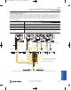
2041 Safety Starter 080709 5/6/2010 11:13 AM Page 6-118 Power Safety Starter Bulletin 109S Typical Wiring Diagrams OL K1 General L1 (2) (T1) (4) (T2) (6) (T3) INCOMING L2 LINES L3 GND K2 1L1 (1) (1) (2) (L1) (T1) (L1) 1L2 (3) (3) (4) (L2) 1L3 (L2) (T2) (5) (5) (6) (L3) GND LUG (L3) (T3) T1 (2) OL (T1) (4) OL (T2) (6) (T3) Principles 1 TB1 2 TB1 K1 (53) (54) K2 (53) (54) T2 MOTOR T3 GND 3 TB1 5 TB1 4 TB1 6 TB1 K1 7 TB1 (71) (72) K2 8 TB1 (71) (72) 120V AC SAFETY CONTROL A1 TB1 9
2041 Safety Starter 080709 5/6/2010 11:13 AM Page 6-119 Power Safety Power Controller Bulletin 2041 600V AC maximum Control Voltage Range 24V DC or 110/120V AC (50/60 Hz) Enclosure Rating Type 12 (IP54) Open Frame System Operational Limits +10%, -15% of the line voltage Estimated Component Life 1,000,000 operations -40…+80° (-40…176°) Operating Temperature, Ambient [C (F)] -25…+40° (-13…104°) Relative humidity 90% noncondensing Approvals CE Marked for all applicable directives TÜV Catego
2041 Safety Starter 080709 5/6/2010 11:13 AM Page 6-120 Power Safety Starter Bulletin 2041 Product Selection Bulletin 2041 cat. nos. can be configured by selecting the appropriate codes from the tables below.
2041 Safety Starter 080709 5/6/2010 11:13 AM Page 6-121 Power Safety Power Controller Bulletin 2041 Typical Wiring Diagram K1 K2 1L1 (2) (1) (1) (2) (T1) (L1) 1L2 (L1) (T1) (4) (3) (3) (4) (T2) (L2) 1L3 (L2) (T2) (6) (5) (5) (6) (T3) (L3) GND (L3) (T3) INCOMING LINES L2 L3 GND T1 T2 MOTOR T3 General L1 GND Principles 120V AC CONTROL POWER FAN A1 TB1 (A1) S22 SAFETY RELAY MSR127TP A2 TB1 (A2) (S22) 1 TB1 (13) (S52) 2 TB1 (13) (S11) 5 TB1 (31) (S12) 6 TB1 (31) TB1 S12 S11 T
2041 Safety Starter 080709 5/6/2010 11:13 AM Page 6-122 Power Safety Starter/Safety Power Controller Bulletin 109S/2041 Approximate Dimensions [mm (in.)] Dimensions are not intended to be used for manufacturing purposes. General Type 12 Enclosure Principles Panel Dimensions (H x W x D) (M2) Height [mm (in.)] C09…C16 12 x 10 x 8 324 (12.75) C23…C30 16 x 12 x 10 368 (14.5) C37…C43 16 x 12 x 10 368 (14.
2030 ElectroGuard 080509 5/6/2010 11:25 AM Page 6-123 Power General ElectroGuard® 330KVA 600/480 Principles 2031-A0110JB-1CNET Power Panel 9- 2030-PJ1204 Pneumatic Isolation Module 2030-RLSJG Remote Lockout Stations M Typical System Description Standard Features The ElectroGuard system is designed to simplify the Lock Out/Tag Out (LOTO) task performed by a machine operator or maintenance personnel. The ElectroGuard system can control single or multiple energy sources simultaneously.
2030 ElectroGuard 080509 5/6/2010 11:25 AM Page 6-124 Power ElectroGuard® Specifications Sequence of Operation General After using the normal stopping method of the machine or process, the machine operator turns a Remote Lockout Station (RLS) handle from the ON to the OFF position.
2030 ElectroGuard 080509 5/6/2010 11:25 AM Page 6-125 Power ElectroGuard® Communication Door Mounted Metering The optional Communication Module allows the ElectroGuard system to communicate status to the process or machine control system. Although the communication module can be field installed, it is recommended that this option be ordered as part of the ElectroGuard system.
2030 ElectroGuard 080509 5/6/2010 11:25 AM Page 6-126 Power ElectroGuard® Product Selection ElectroGuard cat. nos. can be configured by selecting the appropriate codes from the tables below.
2030 ElectroGuard 080509 5/6/2010 11:25 AM Page 6-127 Power Code Description Type 4X watertight stainless steel A 240V 60 Hz/220V 50 Hz F§ Type 4 watertight painted steel/IP65 J Type 12 dusttight/IP54 § Cooling to be supplied by customer. B 480V 60 Hz/440V 50 Hz C 600V 60 Hz/550V 50 Hz G 400…415V 50 Hz H 208V/60 Hz M 500V 50 Hz N 380…400V 50 Hz f f g 2032 Fuse Clip Rating/Type♣ 2033 Circuit Breaker Hp/kW Rating® Factory-Installed Options Hp Code 39 5 Hp 39k 4 kW 40 7.
2030 ElectroGuard 080509 5/6/2010 11:25 AM Page 6-128 Power ElectroGuard® Bulletin 2030 Pneumatic and Hydraulic Isolation Modules General 2030 ⎯ P J a b 120 4 c a Product Descriptor Code Description P Pneumatic isolation module H Hydraulic isolation module Principles b Enclosure Type 1-1/2 in.
2030 ElectroGuard 080509 5/6/2010 11:25 AM Page 6-129 Power ElectroGuard® 2030 ⎯ EU a N F b c 1CNET 1TD d d General Bulletin 2030 Expansion Module a Code Description EU Expansion module Principles Product Descriptor b 4-Port Expansion Module Enclosure Type Expansion Modules may be ordered with an adjustable time-delay feature (1…30 seconds) in order to allow time for the machine operator to shut down drives or other equipment that requires a controlled stop after a RLS handle has bee
2030 ElectroGuard 080509 5/6/2010 11:25 AM Page 6-130 Power ElectroGuard® Bulletin 2030 Remote Lockout Station General 2030 ⎯ RLS J G D a b c a Enclosure Type Code Description C Type 4X watertight stainless steel F Type 4 watertight painted steel/IP65 Principles J Type 12 dusttight/IP54 E Type 7 and 9 hazardous location bolted Remote Lockout Station Remote Lockout Station b The Remote Lockout Station (RLS) is a key component of the ElectroGuard system.
2030 ElectroGuard 080509 5/6/2010 11:25 AM Page 6-131 Power ElectroGuard® Bulletin 2030 Verification Module 2030 ⎯ VM a General C b a Code Description VM Verification module Principles Product Description b Enclosure Type Code Description C Type 4X watertight stainless steel J Type 12 dusttight/IP54 Verification Module 9- Verification Module The optional Verification Module (VM) is connected between the solenoid locking safety switch, similar to a Guardmaster Atlas™ 5 and the Remote L
2030 ElectroGuard 080509 5/6/2010 11:25 AM Page 6-132 Power ElectroGuard® Multiplexer/Permissive Module Sequence of Events for System Multiplexer Module: General When multiple energy sources must be controlled simultaneously or the system must be stopped at a pre-determined stopping point, the LOTO process becomes more complicated with multi-step procedures and locks.
2030 ElectroGuard 080509 5/6/2010 11:25 AM Page 6-133 Power 3. 4. 5. Principles 2. 6-ElectroGuard Logic 11-Cat. No. Index 10-Safety Applications 1. Determine the catalog number of the Safety Isolation System based on the rating of the load(s) to which it will be connected as follows: ⎯ If the Safety Isolation System is connected to a single motor load, the horsepower or kilowatt rating of the system should be determined as follows: a.
08_194_Switches 5/13/2010 1:32 PM Page 6-134 Power IEC Load Switches Bulletin 194E Bulletin 194E IEC Load Switches Standards Compliance 6-IEC Load Switches IEC 60947-1 IEC 60947-3 Low-voltage switchgear and control gear part 3 UL 508 CSA: C22.2 No. 14 Certifications Principles Description 9- Bulletin 194E load switches are designed for use as local motor isolation and disconnect switch applications.
08_194_Switches 5/13/2010 1:32 PM Page 6-135 Power IEC Load Switches Bulletin 194E 194E – A Principles 6-Pole Base Mount 6-Pole Front Mount 32 – 1753 a b c a b c Installation Type Load Size Function/Circuit Diagram Ref.
08_194_Switches 5/13/2010 1:32 PM Page 6-136 Power IEC Load Switches Bulletin 194E 6-IEC Load Switches Product Selection Frequently Ordered1 OFF-ON 3-Pole Switch (includes operating shaft) (Handles listed on page 6-137) Contact Target Configuration X = Contact Closed O = Contact Open OFF-ON 3-Pole Switch (includes operating shaft) Handle Position Function Switching Angle OFF/0 No. of Circuits Principles O O O Front-Mounted Rated Current [A] Hp @ 480V AC 60 Hz 3 Ø Cat. No. Cat. No. 16 7.
08_194_Switches 5/13/2010 1:32 PM Page 6-137 Power IEC Load Switches Bulletin 194E Color Handles (Includes Legend Plate and Control Knob) Bulletin 194L handles are available in both screw fixing and 22.5 mm mounting hole style.
08_194_Switches 5/13/2010 1:32 PM Page 6-138 Power IEC Load Switches Bulletin 194E 6-IEC Load Switches Frequently Ordered 194L Handles — OFF-ON Base/Front-Mounted 3- and 6-Pole Switch Handles (Switch Body listed on page 6-136) Handle Type Degree of Protection E Handle Color Bezel Plate Size For Use With Legend Plate Marking Cat. No. 0-1 194L-HE4E-175 Black/Grey 48 x 48 mm (1-57/64 x 1-57/64 in.
08_194_Switches 5/13/2010 1:32 PM Page 6-139 Power IEC Load Switches Frequently Ordered Switch Kits — OFF-ON Front- and Base-Mounted 3-Pole Switch With Cat. No. 194L-HE6N-175 Red/Yellow Handle Function Switching Angle Rated Current [A] AC23A Rated Power [kW] at 690V AC HP @ 480V AC 60 Hz, 3-Phase Base-Mounted Cat. No. Front-Mounted Cat. No. 25 7.5 10 194E-A25-1753-6N 194E-E25-1753-6N 32 11 15 194E-A32-1753-6N 194E-E32-1753-6N 63 18.
08_194_Switches 5/13/2010 1:32 PM Page 6-140 Power IEC Load Switches Bulletin 194E Bulletin 194E Enclosed Disconnect Load Switches with 194R Handles (with Defeater, suitable for 3 padlocks) 6-IEC Load Switches 194E-FA Painted Steel Enclosure UL Type 3/4/12, IP66 194E-CA Stainless Steel Enclosure UL Type 4/4X, IP66 194E-KA Non-Metallic Enclosure UL Type 3/4/4X, IP66 194E-AA Metallic Enclosure UL Type 1, IP54 194E-DA Stainless Steel Enclosure UL Type 4/4X, IP66 194E-GA Painted Steel Enclosure UL T
08_194_Switches 5/13/2010 1:32 PM Page 6-141 Power IEC Load Switches Bulletin 194E Accessories 6-IEC Load Switches IEC Load Switch Accessories 194E-E16…100 A, Front/Door Mounting (1) 4-Pole Auliliary Contact (1) 2-Pole Auliliary Contact or Grounding Terminal or Additional Pole Principles or 9- Neutral Terminal or (1) 2-Pole Auliliary Contact or (1) 4-Pole Auliliary Contact 194E-A16…100 A, Base/DIN Rail Mounting (1) 4-Pole Auliliary Contact or 10-Safety Applications (1) 2-Pole Auliliary Conta
08_194_Switches 5/13/2010 1:33 PM Page 6-142 Power IEC Load Switches Bulletin 194E Auxiliary Contacts No. of Auxiliary Contacts 6-IEC Load Switches 1 N.O. + 1 N.C. 1 N.O. + 1 N.C.L.B. 2 N.O. + 2 N.C. 1 N.O.E.B. Principles Additional Pole, 1 N.O. 10-Safety Applications 11-Cat. No. Index Neutral Terminal Cat. No.1 194E-A-P11 194E-E16…100 194E-E-P11 194E-A16…100 194E-A-PL11 194E-E16…100 194E-E-PL11 194E-A16…100 194E-A-P22 194E-E16…100 194E-E-P22 194E-A16 194E-A16-PD10 194E-A25...
08_194_Switches 5/13/2010 1:33 PM Page 6-143 Power IEC Load Switches For Use With Cat. No. 3…4 194E-A25/32 194L-G3572 3…4 194EA-40/63 6 194EA-25/32 6 194EA-40/63 3…4 194EA-80/100 No. of Poles For Use With Cat. No. 3…4 194E-A25/32 194L-G3576 6 194EA-25/32 3…4 194EA-40/63 6 194EA-40/63 3…4 194EA-80/100 194E-G3663 194E-G3665 194E-G3664 194E-G3666 Pkg. Qty. Cat. No. 5 194E-G3673 194L-G3572 and G3676 5 194E-G3653 No. of Poles For Use With Cat. No.
08_194_Switches 5/13/2010 1:33 PM Page 6-144 Power IEC Load Switches Bulletin 194E Bulletin 194E Load Switch Cat. No. Shaft Selection for use with 194E and 194L Thermoplastic Enclosures 6-IEC Load Switches 3-Pole Switches (-1753 suffix) 194E-E… 6-Pole Switches (-1756 suffix) 194E-A… Changeover Switches (-3753 suffix) Principles 194E-E… 194E-A… 194E-E… 194E-A… 16 plastic shaft (Cat. No. plastic shaft (Cat. No. 194L-G3380) 194L-G2830) metallic shaft (Cat. No.
08_194_Switches 5/13/2010 1:33 PM Page 6-145 Power IEC Load Switches Other Accessories 194L/194E 22.5 mm Mounting Hole Style Handles (Type B, D) (For Front-Mounted Switches) Cat. No. 194L-HCB-001 Type B 194L-HCDC-001 22.5 mm Mounting Hole Style Handles Key Removal Position (Includes Latch) For Use With 194L-E 12…40 A, 194E-E16…63 A, -1753 194L-HCDD-001 22.5 mm Mounting Hole Style Handles Key Removal Position (Includes Latch) For Use With 194L-E 12…40 A, 194E-E16…63 A, -1753 194L-HCDG-001 Pkg.
08_194_Switches 5/13/2010 1:33 PM Page 6-146 Power IEC Load Switches Bulletin 194E Additional Legend Plates/Frames 6-IEC Load Switches Color Legend Size For Use With Pkg. Quantity Legend Plate Marking Black/Grey Principles Black/Grey 19.2 mm x 49 mm 3/4 in. x 1-59/64 in. 18 mm x 84 mm 11/16 in. x 3-5/16 in. Size 6 Type G and N style handles, Cat. Nos. 194L-HE6G/N Size 8 Type G and N style handles, Cat. Nos. 194L-HE8G/N Cat. No.
08_194_Switches 5/13/2010 1:33 PM Page 6-147 Power IEC Load Switches Bulletin 194E Suitable For No. of Contacts Shaft Use with 194E Switch No.
08_194_Switches 5/13/2010 1:33 PM Page 6-148 Power IEC Load Switches Bulletin 194E Electrical Ratings 6-IEC Load Switches Performance Data 16 A 25 A 32 A 40 A 63 A 80 A 100 A IEC Applications Aux.
08_194_Switches 5/13/2010 1:33 PM Page 6-149 Power IEC Load Switches Bulletin 194E Performance Data 16 A 25 A 32 A 40 A 63 A 80 A 100 A UL/CSA Applications Aux. Contacts Continuous current [A] 16 25 32 40 63 80 100 — Heavy Pilot Duty [AC] A600 A600 A600 — — — — A600 Standard Duty [DC] — — — — — — — Q600 FLA 16 16 16 24 34 56 80 7.
08_194_Switches 5/13/2010 1:33 PM Page 6-150 Power IEC Load Switches Bulletin 194E Approximate Dimensions 6-IEC Load Switches Dimensions are shown in millimeters (inches). Dimensions are not intended to be used for manufacturing purposes. Front Installation Cat. No. 194E-E… 1 (3/64)…5 (13/64) Dia. 3.3 (1/8) Principles 9.5 (3/8) 6-Pole 3-Pole Handles Switch Body 9- 10-Safety Applications 11-Cat. No. Index Cat. No.
08_194_Switches 5/13/2010 1:33 PM Page 6-151 Power IEC Load Switches Bulletin 194E Handles Cat. No.
08_194_Switches 5/13/2010 1:33 PM Page 6-152 Power IEC Load Switches Bulletin 194E Dimensions are shown in millimeters (inches). Dimensions are not intended to be used for manufacturing purposes. 6-IEC Load Switches Base Installation Cat. No. 194E-A… Cat. No. 194E-A Switch Body with Metal Shaft Extension Cat. No. A 194L-G3393 110…235 (4-11/32…9-1/4) 194L-G3394 230…350 (9-1/16…13-25/32) Principles Cat. No.
08_194_Switches 5/13/2010 1:33 PM Page 6-153 Power IEC Load Switches Bulletin 194E Dimensions are shown in millimeters (inches). Dimensions are not intended to be used for manufacturing purposes. Principles 6-IEC Load Switches Base Mounting Cat. No. 194E-A… Thermoplastic Enclosures Poles 3 and 4 Cat. No. 1 1 Height A Width B Knockouts ØD1 118 (4-21/32) 66 (2-19/32) M16/M20 16/20 mm M25/M30 25/30 mm 194E-Y16 F Depth H PG11/PG16 18.5/22.
08_194_Switches 5/13/2010 1:33 PM Page 6-154 Power IEC Load Switches Bulletin 194E Dimensions are shown in millimeters (inches). Dimensions are not intended to be used for manufacturing purposes. 6-IEC Load Switches 194E Enclosed Switches with 194R Handles Principles (4) 5/16 (7.9) dia. mtg. holes (4) 5/16 (7.9) dia. mtg. holes Cat. Nos. 194E-CA16…63, 194E-FA16…63, 194E-AA16…63 Cat. Nos. 194E-CA80…00, 194E-FA80…00, 194E-AA80…00 Cat. Nos. 194E-CA40X…63X, 194E-FA40X…63X, 194E-AA40X…63X 1/2 (11.
08_194_Switches 5/13/2010 1:33 PM Page 6-155 Power IEC Load Switches Bulletin 194E Bulletin 194E IEC Load Switches Bulletin 194E load switches are designed for use as local motor isolation and for disconnect switch applications. They are available in 3- and 4-pole versions with add-on grounding and neutral terminals and auxiliary contacts. Certifications cULus Listed (Box Lug Version) (UL File No. E14841, Guide NLRV, NLRV7) UR Recognized (Bolt-on Version) (UL File No.
08_194_Switches 5/13/2010 1:33 PM Page 6-156 Power IEC Load Switches Bulletin 194E 6-IEC Load Switches Product Selection Frequently Ordered 194E Switches (see Cat. No. Explanation for additional load sizes in 3- and 4-pole configurations) Description No.
08_194_Switches 5/13/2010 1:33 PM Page 6-157 Power IEC Load Switches Accessories Handles 194E - 125...315 A Legend Plate Size 88 x 88 mm 3-15/32 x 3-15/32 in. Red/Yellow 194E-HE8A-175 194E-HE13A-175 194E-125…315 A 88 x 88 mm 3-15/32 x 3-15/32 in. 194E-HE8I-175 ON 130 x 130 mm 5-1/8 x 5-1/8 in. Type I IP65 (UL Type 3/3R/12) Cat. No. 194E-HE13I-175 OFF Black/Grey 90 x 90 mm 3-35/64 x 3-35/64 in. 135 x 135 mm 5-5/16 x 5-5/16 in.
08_194_Switches 5/13/2010 1:33 PM Page 6-158 Power IEC Load Switches Bulletin 194E Neutral Terminal 6-IEC Load Switches Shaft Extension For Use With Cat. No. 194E-A125-160,194E-E125-160 194E-AE160-TN 194E-A250-315,194E-E250-315 194E-AE315-TN 194E-B125-160,194E-F125-160 194E-BF160-TN 194E-B250,194E-F250 194E-BF250-TN 194E-B315,194E-F315 194E-BF315-TN Principles Length For Use With Cat. No.
08_194_Switches 5/13/2010 1:33 PM Page 6-159 Power IEC Load Switches 194E-250 194-315 1000 1000 1000 1000 Rated impulse withstand voltage Uimp [kV] 8 8 8 8 Test voltage 1 min [kV] 3.5 3.5 3.5 3.
08_194_Switches 5/13/2010 1:34 PM Page 6-160 Power IEC Load Switches Bulletin 194E IEC Performance Data for 194E, Continued 6-IEC Load Switches DC Switching Capacity 194E-125 194E-160 194E-250 194E-315 e Rated current I Rated voltage [V] No. Poles in series DC-21A 60 3 [A] 125 160 250 315 For resistive loads T≤1 ms 110 3 [A] 110 140 220 280 [A] 45 55 85 110 Principles Rated power Pe 220 3 Rated voltage [V] No.
08_194_Switches 5/13/2010 1:34 PM Page 6-161 Power IEC Load Switches Bulletin 194E Protection class according to IEC 529 Front side Front unit Box lugs1 Bolt-on straight version1 [Million operations] Fine strands, 1 conductor Gauge No. 194E-315 IP66 — — — — IP66 IP66 IP66 IP20 IP20 IP20 IP20 IP20 IP20 IP20 IP20 — — — — 0.1 0.1 0.075 0.075 Box lugs — max.
08_194_Switches 5/13/2010 1:34 PM Page 6-162 Power IEC Load Switches Bulletin 194E Approximate Dimensions Dimensions are shown in millimeters (inches). Dimensions are not intended to be used for manufacturing purposes. 6-IEC Load Switches Front-Installation Box Lugs, 3- and 4-Pole max.
08_194_Switches 5/13/2010 1:34 PM Page 6-163 Power IEC Load Switches Bulletin 194E Dimensions are shown in millimeters (inches). Dimensions are not intended to be used for manufacturing purposes. 6-IEC Load Switches Base-Mounting Box Lugs, 3- and 4-Pole Principles max. D mm2 [A] A B C D E F G H I L 125 91 (3-19/32) 112 (4-13/32) 38 (1-1/2) 95 (3-23/64) 2 (3/32) 118 (4-5/8) 6.
08_194_Switches 5/13/2010 1:34 PM Page 6-164 Power IEC Load Switches Bulletin 194E Dimensions are shown in millimeters (inches). Dimensions are not intended to be used for manufacturing purposes. 6-IEC Load Switches Box Ground and Neutral Terminal FRONT BASE Principles Switch Body 194E-F 9- [A] A B C D E F 125 37.8 (1-1/2) 64 (2-17/32) 108 (4-1/4) 37.8 (1-1/2) 64 (2-17/32) 108 (4-1/4) 160 37.8 (1-1/2) 64 (2-17/32) 108 (4-1/4) 37.8 (1-1/2) 64 (2-17/32) 108 (4-1/4) 250 52.
08_194_Switches 5/13/2010 1:34 PM Page 6-165 Power IEC Load Switches Bulletin 194E Dimensions are shown in millimeters (inches). Dimensions are not intended to be used for manufacturing purposes. 6-IEC Load Switches Terminal Cover A B 125 76.2 (3) 95 (3-3/4) 160 76.2 (3) 95 (3-3/4) 250 88 (3-15/32) 109.5 (4-5/16) 315 88 (3-15/32) 109.
08_194_Switches 5/13/2010 1:34 PM Page 6-166 Power IEC Load Switches Bulletin 194E Dimensions are shown in millimeters (inches). Dimensions are not intended to be used for manufacturing purposes. 6-IEC Load Switches Handles (Type 194E-HE-8A-8I-8G-8N) Principles 9Handles (Type 194E-HE-13A-13I-13G-13N) 10-Safety Applications 11-Cat. No. Index 27 Logic Type A and I Type G and N Additional Name Plate Frame and legend snaps on to handle bezel. Fits size 8 and 13 handles.