0 sziip!c!g OPERATOR’S MANUAL Chipper Vacuum 5125 Series Mfg. No. 1692371 1692562 Description Model 5/25,5HP Chipper Vacuum Model 5/25,5HP Chipper Vacuum 5125 Series Mfg. No. 1692373 1692564 Description Model 6/25,6HP Chipper Vacuum Model 8/25,6HP Chipper Vacuum 8/25E Series M f g . N o . .
MANUFACTURING, INC. 500 N Spring Street I PO Box 997 Port Washington, WI 53074-0997 www.simplicitymfg.com 0 Copyright 1998, Simplicity Manufacturing, Inc. All Rights Reserved. Printed in USA.
Baker Chipper/Shredder OPERATOR’S MANUAL Chipper Vacuum 5125 Series Mfg. No. 1692372 1692583 Description Model 5/25,5HP Chipper Vacuum Model 5/25,5HP Chipper Vacuum 8125 Series Mfg. No. 1692374 1692585 Description Model 8/25,8HP Chipper Vacuum Model 8/25,8HP Chipper Vacuum 8/25E Series Mfg. No.
Baker 500 N. Spring Street \ P.O. Box 997 Port Washington, WI 53074.0997 USA 0 Copyright 1998, Simplicity Manufacturing, Inc. All Rights Reserved. Printed in USA.
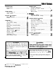
INTRODUCTION NORMAL CARE Scheduled Maintenance . . . . . . . . . . . . . . . . . . . . . . . . . . . . . . . . . 19 Servicing the Chipper Vacuum . . . . . . . . . . . . . . . . . . . . . . . 19 Bag C a r e . :.:.......................................... 21 Battery Maintenance . . . . . . . . . . . . . . . . . . . . . . . . . . . . . . . . . . . . . . . 21 Model Identification . . . . . . . . . . . . . . . . . . . . . . . . . . . . . . . . . . . . . . . . . . . 2 Description . . . . . . . . . . . . . . .
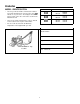
Introduction MODEL IDENTIFICATION l l l Record your model number, manufacturer number and serial numberfrom the I.D. tag in the space provided t for easy reference. The Chipper Vacuum I.D. tag is located on the side of the unit as shown in the illustration below. Refer to the engine manufacturer’s owner’s manual for the location of the engine serial number. Model Mfg. No.
DESCRIPTION rocks, gravel, and other debris before use. All materials and other debris that could damage the shredding hammers should be removed and properly disposed of before starting the unit. General The shredding chamber is designed to shred materials that have been vacuumed directly into the unit through the extra-wide vacuum intake nozzle or through the flexible vacuum hose, eliminating the need to manually load or feed material into the shredder.
A The Safety Alert symbol shown to the left is used to alert you to important safety information that must be read, fully understood, and followed at all times when handling, transporting, operating, servicing, or storing your Chipper Vacuum. Each safety alert symbol is followed by a “signal word” that advises you of the relative intensity, or level, of the hazard the safety alert instructions pertain to.
l l l l l Never store the fuel container or Chipper Vacuum indoors where there is a possibility of contact with any ignition source such as a spark, open flame, pilot light, heating element, or smoking materials. A CAUTION SPARK/FIRE HAZARD GAS ENGINES MAY REQUIRE A SPARK ARRESTER FOR SAFE OPERATION Never attempt to test or operate the unit indoors or in an enclosed area. Engine exhaust contains carbon monoxide, an odorless, colorless, and tasteless gas.
Safety Rules l l l l l l l Never leave the machine running unattended. Always turn off the engine, wait ior the rotor to come to a complete stop, and disconnect the spark plug before leaving the area. Always move the unit to a safe storage area for prolonged idle periods. followina: Never allow children to operate the machine. Do not allow adults to operate it without proper instruction. b. Check for loose parts, and loose or missing hardware, and repair or replace as reauired.
Safety Rules storage preparations before storing the unit for prolonged periods. equipment can result in serious injury, damage to equipment, and voiding of your warranty. TRANSPORTING AND STORAGE l l l l l l If you must travel across rock, gravel, or other debris-covered terrain, set the engine speed control to Wow”, and close the variable suction control flap by moving the selector lever to the “closed” position. Never lift the unit using the fuel tank, vacuum intake areas, or covers for support.
Features & Controls MAJOR COMPONENTS OPTIONAL HOSE KIT ASSEMBLY Engine . Chipper Cone/Chipper Knives . Shredding Chamber . Drive Wheels E. Frame F. Discharge Bag G. H. I. J. K. L. 8 Vacuum Hose w/Nozzle (optional) Vacuum Nozzle w/Variable Suction Control Vacuum Hose Intake Handle Assembly Transmission (not shown) Discharge Tube.
CONTROLS A. Choke The choke controls the fuel to air ratio, and helps make cold starts easier by providing a rich, easily-ignited fuel mixture. B. Throttle The throttle controls engine speed, and allows you to conserve fuel by powering down during idle periods, or to achieve optimal chipping/shredding/vacuuming power by running the engine at full speed. C.
Operation 2. Inspect the chipper cone and make sure that it is firmly attached to the shredder housing. SITE LOCATION 1. Select an area that will provide stable footing for both the Chipper Vacuum and the operator. Do not operate on wet, slippery surfaces, or in areas with heavy pedestrian traffic that may distract you from alert operation of the unit. 3. Check all parts to ensure that they are properly attached and that all fasteners are properly tightened. 4.
Operation Starting The Engine - Manual Start Units 1. Move choke lever to full choke position. 2. Move throttle lever to “fast”. 3. Place foot on front wheel to hold unit firmly in place, and adopt a stable stance. 4. Pull starting rope out slowly one time and allow to return normally. Choke & throttle controls 5. Pull starting rope out with a steady pull, and allow rope to return normally. 6. When engine starts, gradually move choke lever to “no choke” position. 7.
Operation Drive Speed Selector Speed Selector Lever Forward speed is selected using the speed control lever mounted on the right side of the handle. The speed control lever has three positions: slow, medium or fast (Figure 3). The ability to select different speeds for differing types of waste material pick-up and varying surface conditions helps give you precise control over the unit, which is further enhanced by the 3-position vacuum height adjustment and 4-position vacuum intake opening adjustment.
Operation l l l Hold tree limbs and branches carefully as they are being put into the chipper cone, releasing your grip as soon as the self-feeding action of the chipper knives begin to pull the material in. Longer pieces may have a tendency to twirl around forcefully as they are being drawn into the chipping knives. Hold the material safely away from the chipper cone area until the material is properly controlled by the chipper cone.
Operation 4. lnserl the connector end of the vacuum hose into the intake opening, using care to fully seat the connector in the opening. If the connector is not fully inserted, and electrical interlock switch will keep the unit from starting or running (Figure 6). 5. Place the hand-held vacuum intake nozzle in the area to be vacuumed, using care to avoid twisting and minimize bends in the hose. 6.
Operation 2. Remove the spark plug wire from the spark plug to prevent the possibility of inadvertent starting. On electric-start models, remove the key to prevent anyone from inadvertently activating the electric start feature. Although the unit won’t start with the spark plug removed, the rotor will turn, and serious injury could result if your hands are in the area of the rotor or chipper knives. 3.
Operation A safe collection area should be located where children, pets, and bystanders will not come into contact with chipped material as it is being discharged, or be hit by deflected pieces that may ricochet away from the collection area with great force. When using direct discharge, check the discharge area frequently for accumulation of material near the discharge port, and make sure the material can be safely ejected away from the unit.
Operation slides smoothly into place in one of four slots (Figure 9). To adjust the opening of the vacuum intake nozzle flap: l 1. Grip the curved portion of the lever arm, 2. Pull the lever out of the present slot, 3. Slide the lever into the desired slot. l Vacuum Intake Nozzle Height Position The vacuum intake nozzle height adjustment is located at the rear of the frame on the left side of the unit (Figure 10). This adjustment controls the height of the vacuum intake nozzle above the ground.
If you are unsure about processing a material not covered in the guide below, contact your local authorized dealer, or call our Customer Service Department at 414-284-6786 for assistance before proceeding. WASTE MATERIALS GUIDE Your Chipper Vacuum is designed to efficiently process a wide variety of organic yard and garden waste materials.
Normal Care SCHEDULED MAINTENANCE Your Chipper Vacuum has been designed to provide you with years of reliable operation. Keeping your Chipper Vacuum in top running condition will prolong its life, and help you obtain optimum performance whenever you wish to chip or shred yard or garden waste. Please read this normal care schedule, and observe these recommended care operating intervals to extend the life of your unit.
NormalCare Clean Engine Air Intake Area The engine is air-cooled, and requires unobstructed air flow into and around the engine. The cooling fins on the engine cylinder head area must also be kept clear of chipper and shredding deposits, as well as any other build-up of debris that could prevent heat from radiating away from the engine (Figure 14). To clean the air intake area, remove any external material build-up, and then blow out the area using a stream of compressed air.
Normal Care and clean out if required. Always shut engine off and remove the spark plug wire from the spark plug before reaching into the housing to clear material. fluid levels to run down below full may result in erratic starting performance, or inability of the battery to provide adequate power to operate the starter motor. For stubborn debris, the vacuum nozzle housing can be removed from the unit following the steps in the hammer service section of this manual, and hosed out with a garden hose.
Storage TEMPORARY STORAGE l (30 Days Or Less) l Here’s a quick checklist of things to do when storing your Chipper Vacuum temporarily, or between uses: l l l l l l l l Keep the unit in an area away from where children may come into contact with it. When this equipment is stopped for service, inspection, or storage, or to change an accessory, operators shall make sure the spark plug wire is disconnected from the spark plug.
Troubleshooting & Repair GENERAL TROUBLESHOOTING A The troubleshooting guide below lists the most common problems, causes and remedies. Never attempt to perform any of these procedures with the engine/motor running. Always turn the unit off, let the rotor come to a complete stop, and disconnect the spark plug wire or power cord Ezsre attemptmg to correct any operatmg prob- See the service information on the following pages for instructions on how to do most of these minor repairs yourself.
Troubleshooting & Repair POWER DRIVE TROUBLESHOOTING Power Drive won’t engage. I I Bail lever cable too loose. Bail lever cable end not engaged in clutch lever. l Drive belt broken or loose. l Drive chain(s) broken. l Drive chain(s) off sprocket. l Crankshaft key broken or missing from unit. 9 Clutch lever obstructed. l l l l Move clip up to next link. Insert cable end in clutch lever. l Repair or replace. Repair or replace. Reinstall chain(s) on sprocket. Replace key. l Clear obstruction.
Troubleshooting %I Repair Figure 15. Remove Cover Panel Fasteners Figure 16. Lift Top Cover Up And Away From Unit Figure 17. Remove Right Cover Panel Fasteners Figure 16. Remove Right Cover SHREDDING HAMMERS 1. Turn the unit off, allow the rotor to stop completely, and disconnect the spark plug wire. 2. Remove top cover by prying up panel fasteners with a flat blade screwdriver. Pry panel fastener heads up to permit gripping with fingers, then pull fastener heads to remove fastener (Figure 15). 3.
Troubleshooting & Repair Figure 20. Pull Drive Pulley Bearing Plate And Slide Drive Belt Off Pulley Figure 21. Pull Drive Pulley Bearing Plate Assembly Out Of Vacuum Nozzle Housing Figure 22. Remove Vacuum Nozzle Housing Nuts Figure 23. Pull Off Safety Interlock Wire At Spade Terminal 5. Pull the drive pulley bearing plate straight out, and lift the drive belt off the pulley to permit complete removal of the plate assembly (Figure 20).
Troubleshooting & Repair Figure 25. Disassemble Variable Suction Adjustment Control Bracket From Engine Figure 26. Remove Vacuum Nozzle Housing 9. Using a i/2” socket wrench and i/2” box wrench, remove the hex head screw and hex nut that secures the variable suction adjustment control bracket to the engine block base (Figure 25). 10. Lift the vacuum nozzle housing away from the shredder housing and tilt it up slightly to clear the right front wheel as it is removed from the unit (Figure 26). 1 I.
Troubleshooting & Repair iic: D. E. F. G. H. I. J. K. L. Rotor Spacer J Hammer (2) Flat Washer 318 Lock Washer 310 Capscrew 318-16 x 2” Capscrew 318-f 6 x 1” Triangular Hammer (2) Bushing, Flanged Cap Screw 5/16-18 x 5/8” 5116 Lock Washer Chipper Knife (2) ‘2733 Figure 29. Proper Hammer Assembly CHIPPING KNIVES 15. Rotate the rotor to move the next hammer into position for servicing, and repeat step 14.
Troubleshooting & Repair igure 30. Remove Left Cover Panel Fasteners Figure 31. Remove Left Cover , Figure 32. Remove Rear Panel Fasteners Figure 33. Remove Rear Panel 8. Loosen the discharge tube hex nuts on the right side of the discharge tube, providing approximately i/8” clearance between the hex nut and the tube (Figure 34). 9. Using a l/2” socket wrench and i/2” box wrench, remove the hex head cap screw and hex nut securing the discharge tube to the top brace (Figure 35). 10.
Troubleshooting & Repair Figure 36. Loosen Discharge Tube Hex Head Nuts Left Side Figure 35. Remove Discharge Tube Hex Head Cap Screw And Hex Nut 13. Rotate the rotor to move the first chipping knife into position at the rear opening in the shredding chamber. Pulling slowly on the starter rope will make the rotor rotate. 14. Insert a l/Z” thick x 1 l/2” - 2” wide x IO - 12” long piece of wood into the chipping/shredding chamber under the sharp edge of the chipper knife.
Troubleshooting & Repair Front View Side View gure 39. Chipper Knife Minimum Distance ounting Holes To Bevel Edge l Figure 40. Lift Off Idler Pulley Spring Chipper knives require a 30” bevel on the cutting edge (as shown in figure 39) for efficient chipping action. * Contact your local dealer or blade sharpening service if you prefer not to sharpen the blades yourself. 19.
Troubleshooting & Repair Figure 44. Pull Idler Pulley Assembly Back And Wrap Drive Belt Around Upper Idler Pulley Figure 43. Wrap Drive Belt Around Lower Idler Pulley And Angled Pulley DRIVE BELT 1. The drive belt may be accessed by removing the top, right, and rear covers as shown in previous sections. 2. Remove the drive pulley bearing plate and slip off the drive belt as shown in Figures 19 - 21. 3. Lift the idler pulley spring off the threaded stud, and release tension on the idler pulley assembly.
Troubleshooting & Repair, Figure 47. Reconnect Idler Pulley Tension Spring Figure 48. Drive Belt Installed Position On Pulleys 9. Lift the drive belt over the edge of the drive pulley and engage the pulley, beveled edge in, and slide the drive belt pulley plate and drive shaft into position. Install the two hex head screws and lock washers removed earlier, and tighten securely (Figure 46). 10.
Troubleshootin# #I Repair Damaged chains may be replaced by first loosening tension, then disconnecting master link (front chain only) or removing complete chain (rear chain only), and installing new chain on sprockets. Front Drive Chain 1. Loosen hex nut that locks sprocket in position, and move sprocket forward or backward until chain flexes approximately i/8” when pressed midway between sprockets. Tighten hex nut securely when proper tension is reached on chain (Figure 49). 2.
4. See figure 52. Reattach the rod to the front axle with the clip. NOTE: Changing the rod length will affect the ground clearance measurement at all height ranges and may be used to make fine adjustments to the nozzle height at any position desired. CLUTCH CABLE The clutch cable does not require service. If the clutch cable should become detached from the clutch lever, follow these steps: 1. Remove the vacuum nozzle housing as illustrated in the hammer service section of this manual. 2.
Options & Accessories VACUUM ATTACHMENT This easy-to-add accessory allows the Chipper Vacuum to be equipped with a vacuum hose and other attachments to help simplify pick up of lightweight materials such as leaves and grass clippings. It can also be adjusted to vacuum without disturbing landscaping material such as decorative rock.