Micro-Pro II MP-200 / 300 Series Instruction Manual 0901052 Rev: H (05/13) Page 1 of 16
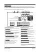
TABLE OF CONTENTS Introduction ........................................................................................................... 3 Circuit Board Diagram .......................................................................................... 3 Installation ............................................................................................................ 4 Plumbing ..............................................................................................................
INTRODUCTION Micro-Pro II warewash systems provide the versatility of probe or probeless detergent control through advanced microprocessor design. With the capability of controlling up to three products, the choice of liquid or dry detergent, and the choice of single or dual transformer configuration, virtually any warewash application can be accommodated. The Micro-Pro II warewash control features simplicity and versatility.
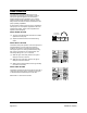
INSTALLATION PRESSURE SWITCH PLUMBING (optional) Mount the unit on a nearby wall (using suitable hardware) or on top of the dishwasher if desired. Try to keep the unit within three feet from the final rinse line to avoid long tubing runs. Install pressure switch kit. Thread the male end of the ―tee‖ fitting into the rinse line on the dishwasher, and connect the poly tubing from the rinse pump into the end opposite the male threads, using the checkvalve provided.
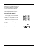
PROBE INSTALLATION (if required) DETERGENT POWER SIGNAL (1) Install the probe in the wash tank below the water level. It should be away from incoming water supplies, near the recirculating pump intake, and 3 to 4 inches from corners, heating elements, or the bottom of the tank. If an existing mounting hole cannot be located, use of a 7/8" hole saw or punch may be desired. A detergent power signal is required to activate the detergent probe sensing or probeless initial charge.
RINSE OPERATION The rinse pump will operate whenever the rinse transformer is energized (if so equipped) or when a rinse power signal is applied to the circuit board, whether directly from the dishwasher, or by using a pressure switch (single transformer version). A rinse delay feature and rinse limit feature maximize the rinse pump operating capabilities. A prime button, located on the front cover, will allow the rinse pump to run at full speed, regardless of the rinse potentiometer setting.
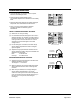
SANITIZER OPERATION A selector switch sets the sanitizer pump to operate with detergent feed, or with rinse feed. The sanitizer pump will run simultaneously with detergent or rinse, whether using probe or probeless mode, rinse delay or rinse limit. A prime button, located on the front cover, will allow the sanitizer pump to run at full speed, regardless of the sanitizer potentiometer setting. Main power must be applied to the system to prime the pump, a signal is not necessary.
PROBE OPERATION With the detergent power ―on‖, the conductivity probe senses detergent concentration. When concentration drops below the setpoint, the control automatically turns on detergent feed. Low and high concentration ranges allow easy setting on all types of water conditions. When the detergent concentration is within 15% of the setpoint, the control automatically pulse feeds (3 seconds on / 2 seconds off) to prevent over-use of chemical.
PROBELESS OPERATION Controls detergent concentration without a probe, based on timed detergent feed. Initial charge time feeds detergent to the concentration setpoint when dishmachines are initially filled. Recharge time feeds detergent to maintain detergent setpoint as rinse water dilutes the dishmachine. Door or conveyor switch selection optimizes SLIDE RIGHT TO ACTIVATE probeless operation for different types of dishwashers.
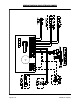
WIRING DIAGRAM (SINGLE TRANSFORMER) Page 10 of 16 0901052 Rev: H (05/13)
WIRING DIAGRAM (TWO TRANSFORMER) 0901052 Rev: H (05/13) Page 11 of 16
ASSEMBLY DIAGRAM (SINGLE TRANSFORMER) Page 12 of 16 0901052 Rev: H (05/13)
ASSEMBLY DIAGRAM (TWO TRANSFORMER) 0901052 Rev: H (05/13) Page 13 of 16
Page 14 of 16 0901052 Rev: H (05/13)
0901052 Rev: H (05/13) Page 15 of 16
DISCLAIMER Knight LLC does not accept responsibility for the mishandling, misuse, or non-performance of the described items when used for purposes other than those specified in the instructions. For hazardous materials information consult label, MSDS, or Knight LLC. Knight products are not for use in potentially explosive environments. Any use of our equipment in such an environment is at the risk of the user, Knight does not accept any liability in such circumstances.