Print Vendor Instructions Paper Size: How to use this file Operator’s Manuals • 11x17 • Body - 50 lbs brilliant white offset or equivalent • Cover - on pre-printed two tone “Swash” stock. Press: • Body - 1 color, 2-sided • Cover - 1 color, 1 sided Bindery: • Saddle stitch, face trim *if too thick for saddle stitch, tape bind Covers: • FRONT COVER is present at the beginning of the file. • BACK COVER is the page immediately after the front cover.
THIS PAGE INTENTIONALLY BLANK (FOR PLACEMENT ONLY - DO NOT PRINT)
OPERATOR’S MANUAL Citation Series 21HP Zero-Turn Riders Mfg. No. 2690444 Description Simplicity 21HP Citation Zero-Turn Rider with 48” Mower 23HP Zero-Turn Riders Mfg. No. 2690445 Description Simplicity 23HP Citation Zero-Turn Rider with 52” Mower 5100324 Revision 02 Rev.
M A N U FA C T U R I N G , I N C . 500 N Spring Street / PO Box 997 Port Washington, WI 53074-0997 www.simplicitymfg.com © Copyright 2006, Simplicity Manufacturing, Inc. All Rights Reserved. Printed in USA.
Table of Contents Troubleshooting, Adjustments & Service .......23 Safety Rules & Information ................................2 Identification Numbers .......................................7 Safety Decals .......................................................8 Safety Interlock System......................................9 Features & Controls ..........................................10 Troubleshooting the Rider .....................................23 Troubleshooting the Mower ...........................
Safety Rules and Information Read these safety rules and follow them closely. Failure to obey these rules could result in loss of control of unit, severe personal injury or death to you, or bystanders, or damage to property or equipment. This mowing deck is capable of amputating hands and feet and throwing objects. The triangle in text signifies important cautions or warnings which must be followed. GENERAL OPERATION enough to protect themselves and others from injury. 19.
Safety Rules and Information SLOPE OPERATION WARNING Slopes are a major factor related to loss-of-control and tipover accidents, which can result in severe injury or death. Operation on all slopes requires extra caution. If you cannot back up the slope or if you feel uneasy on it, do not operate on it. Control of a walk-behind or ride-on machine sliding on a slope will not be regained by the application of the brake.
Safety Rules and Information SERVICE AND MAINTENANCE 12. Do not use gasoline containing METHANOL, gasohol containing more than 10% ETHANOL, gasoline additives, or white gas because engine/fuel system damage could result. 13. If the fuel tank must be drained, it should be drained outdoors. 14. Replace faulty silencers/mufflers. 15. Maintain or replace safety and instruction labels as necessary. 16. Use only factory authorized replacement parts when making repairs. 17.
Safety Rules & Information ROLL BAR INSTRUCTIONS • BEFORE FIRST TIME USE - Inspect the ROLL BAR structure and mounting hardware for: For models equipped with factory-installed Roll Over Protection System (ROPS). 1) Check to make sure the machine GVW (Gross Vehicle Weight), including attachments, restrained payload, fuel and operator, is not in excess of the maximum weight specified on the ROLL BAR label.
Safety Rules & Information WARNING Failure to properly inspect and maintain the seat belt can cause serious injury or death. INSPECTION AND MAINTENANCE OF THE ROLL BAR SEAT BELT • The seat belt like the ROLL BAR, needs to be periodically inspected to verify that the integrity has not been compromised through normal machine use, misuse, age degradation, modifications, or a roll over. If the seat belt does not pass all of the following tests, it should be replaced.
Identification Numbers Identification Numbers SA PL North American / CE Models E 269XXXX SA Mfg. No.: M Identification Tag 2005 dB(A) M kW: XXX Engine RPM XXXX LpA: XXX dB(A) Vibration @ Wheel: XXX m/s² Vibration @ Seat: XXX m/s² CE Models (Only) PL PRODUCT Simplicity Mfg. Inc.
Safety Decals SAFETY DECALS This unit has been designed and manufactured to provide you with the safety and reliability you would expect from an industry leader in outdoor power equipment manufacturing. All DANGER, WARNING, CAUTION and instructional messages on your rider and mower should be carefully read and obeyed. Personal bodily injury can result when these instructions are not followed. The information is for your safety and it is important! The safety decals below are on your rider and mower.
Safety Icons & Interlock System SAFETY INTERLOCK SYSTEM This unit is equipped with safety interlock switches. These safety systems are present for your safety, do not attempt to bypass safety switches, and never tamper with safety devices. Check their operation regularly. Operational SAFETY Checks Test 1 — Engine should NOT crank if: • PTO switch is engaged, OR • Parking brake is not engaged, OR • Motion control handles are not in the NEUTRAL position.
Features & Controls Figure 1. Control Locations CONTROL FUNCTIONS The information below briefly describes the function of individual controls. Starting, stopping, driving, and mowing require the combined use of several controls applied in specific sequences. To learn what combination and sequence of controls to use for various tasks see the OPERATION section. Choke Deck Lift Pedal, Cutting Height Adjustment Pin & Deck Lift Lock Lever Close the choke for cold starting.
Features & Controls Ignition Switch Fuel Tank Cap The ignition switch starts and stops the engine, it has three positions: To remove the cap, turn counterclockwise. OFF Stops the engine and shuts off the electrical system. RUN Allows the engine to run and powers the electrical system. START Cranks the engine for starting. NOTE: Never leave the ignition switch in the RUN position with the engine stopped–this drains the battery. Fuel Level Gauge Displays the fuel level in the tank.
Operation GENERAL OPERATING SAFETY CHECKS BEFORE STARTING Before first time operation: • Check that crankcase is filled to full mark on dipstick. See the engine Operator’s Manual for instructions and oil recommendations. • Make sure all nuts, bolts, screws and pins are in place and tight. • Adjust the seat position, and make certain you can reach all controls from operator’s position. • Fill the fuel tank with fresh fuel. Refer to engine manual for fuel recommendations.
Operation WARNING MOWING 1. Engage the parking brake. Make sure the PTO switch is disengaged, the motion control levers are locked in the NEUTRAL position and the operator is on the seat. 2. Start the engine (see STARTING THE ENGINE). 3. Set the mower cutting height. 4. Set the throttle to FULL. 5. Engage the PTO by pulling up on the PTO switch. 6. Begin mowing. See Section LC for tips on mowing patterns, lawn care, and trouble shooting information. 7. When finished, shut off the PTO. 8.
Operation ZERO TURN DRIVING PRACTICE Smooth Travel The lever controls of the Zero Turn rider are responsive . The lever controls of the Zero Turn rider are responsive, and learning to gain a smooth and efficient control of the rider’s forward, reverse, and turning movements will take some practice. The BEST method of handling the ground speed control levers is in three steps — as shown in Figure 3.
Operation Practice Turning Around a Corner Practice Turning In Place While traveling forward bring one handle gradually back toward neutral. Repeat several times. To turn in place, “Zero Turn,” gradually move one ground speed control lever forward from neutral and one lever back from neutral simultaneously. Repeat several times. NOTE: To prevent pivoting directly on the tire tread, it is best to keep both wheels going at least slightly forward.
Operation RAISE & LOWER THE ROLL BAR C To lower the roll bar: 1. Pull the hair pin clips (A, Figure 9) out of the retainer pins (B). 2. Push or pull the top of the roll bar (C) forward against the rubber stops (D) and remove the retainer pins (B). 3. Lower the roll bar and reinstall the retainer pins and hair pin clips to secure the roll bar in the down position (see insert, Figure 10). D C To raise the roll bar: A 1. Pull the hair pin clips (A) out of the retainer pins (B) and remove the retainer pins.
Operation ATTACHING A TRAILER A The maximum weight of a towed trailer should be less than 200 lbs (91kg). Secure the trailer with a appropriately sized clevis pin (A, Figure 10) and clip (B). Excessive towed loads can cause loss of traction and loss of control on slopes. Reduce towed weight when operating on slopes. The surface being driven on greatly impacts traction and stability. Wet or slippery surfaces can greatly reduce traction and the ability to stop or turn.
Regular Maintenance MAINTENANCE SCHEDULE The following schedule should be followed for normal care of your rider and mower. You will need to keep a record of your operating time. Determining operating time is easily accomplished by observing the elapsed time recorded by the hour meter.
Regular Maintenance CHECK TIRE PRESSURES Tire pressure should be checked periodically, and maintained at the levels shown in the chart. Note that these pressures may differ slightly from the “Max Inflation” stamped on the side-wall of the tires. The pressures shown provide proper traction, improve cut quality, and extend tire life. Tire Pressure Front 25 psi (1,72 bar) Rear 15 psi (1,03 bar) Figure 11.
Regular Maintenance LUBRICATION Lubricate the unit at the locations shown in Figures 13 through 16 as well as the following lubrication points. Grease: • • • • front caster wheel axles & yokes deck lift pivot blocks mower deck spindles mower deck idler arm Use grease fittings when present. Disassemble parts to apply grease to moving parts when grease fittings are not installed. Figure 13. Deck Lubrication Not all greases are compatible.
Regular Maintenance CHECK HYDRAULIC OIL LEVEL 1. Before removing the reservoir cap, make sure the area around the reservoir cap and fill neck of the reservoir is free of dust, dirt, or other debris. 2. Unscrew the reservoir cap (B, Figure 17). 3. Look down the filler neck of the hydraulic oil reservoir (A, Figure 17) and observe the oil level. When cold, the oil level should be approximately 4” (10 cm) below top of the filler neck. 4.
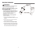
Regular Maintenance SERVICING THE MOWER BLADES 1. Blades should be sharp and free of nicks and dents. If not, sharpen blades as described in the following steps. 2. To remove blade for sharpening, use a 1” wrench on the flats of the spindle shaft while removing the blade mounting bolt with a 15/16” wrench (Figure 19). 3. Use a file to sharpen blade to fine edge. Remove all nicks and dents in blade edge. If blade is severely damaged, it should be replaced. 4. Balance the blade as shown in Figure 20.
Troubleshooting Adjustments & Service TROUBLESHOOTING WARNING While normal care and regular maintenance will extend the life of your equipment, prolonged or constant use may eventually require that service be performed to allow it to continue operating properly. To avoid serious injury, perform maintenance on the tractor or mower only when the engine is stopped and the parking brake engaged.
Troubleshooting, Adjustment & Service Rider Troubleshooting Continued. PROBLEM CAUSE REMEDY Engine runs, but rider will not drive. 1. 1. Turn valve(s) clockwise to close. Rider drive belt slips. Brake will not hold. Rider steers or handles poorly. 2. 3. 4. 1. 2. Hydraulic release valve(s) in “open” position. Belt is broken. Drive belt slips. Brake is not fully released. Pulleys or belt greasy or oily. Tension too loose. 3. 1. 2. 1. 2. Belt stretched or worn. Brake is incorrectly adjusted.
Troubleshooting, Adjustment & Service SEAT ADJUSTMENT See Figure 22. The seat can be adjusted forward and back. Move the lever towards the left, position the seat as desired, and release the lever to lock the seat into position. GROUND SPEED CONTROL LEVER ADJUSTMENT Seat Adjustment Lever The control levers can be adjusted in three ways. The alignment of the control levers, the placement of the levers (how close the ends are to one another) and the height of the levers can be adjusted. Figure 22.
Troubleshooting, Adjustment & Service PARKING BRAKE ADJUSTMENT 1. Disengage the PTO, engage the parking brake, stop the engine and remove the ignition key. 2. Raise the seat plate. 3. Locate the brake spring (A, Figure 25). 4. With the parking brake engaged, measure the compressed spring length. The spring should be 1-15/16” - 2” (4,9 - 5,1 cm) when compressed. 5. If the spring is not within this range, release the parking brake and turn the adjustment nut (B) to compress or release the spring. 6.
Troubleshooting, Adjustment & Service REAR SUSPENSION ADJUSTMENT POSITION #1 (FACTORY SET) The shock assembly can be adjusted in two ways to allow the operator to customize the ride according to operator’s weight and/or operating conditions. You have the option of adjusting the spring pre-load and/or the upper mounting position. POSITION #2 Items to consider before adjusting the suspension.
Troubleshooting, Adjustment & Service A B B B C B Figure 28. Adjust PTO Clutch A. Window B. Adjustment Nut C. .016”-.018” (0,40-0,45mm) Feeler Gauge A Figure 27. PTO Clutch Adjustment A. Adjustment Window (Qty. 3, one shown) B. Adjustment Nut PTO CLUTCH ADJUSTMENT WARNING Check the PTO clutch adjustment after every 100 hours of operation. Also perform the following procedure if the clutch is slipping or will not engage, or if a new clutch has been installed.
Troubleshooting, Adjustment & Service RETURN-TO-NEUTRAL ADJUSTMENT C To determine if it is necessary to adjust the neutral return, perform the following steps. 1. Disengage the PTO, engage the parking brake and turn off the engine. 2. Move the ground speed control levers into the operating position, pull levers rearward and release. 3. Move the ground speed control levers out towards the neutral position.
Troubleshooting, Adjustment & Service MOWING HEIGHT ADJUSTMENT The cutting height adjustment pin (A, Figure 31) controls the mower cutting height. The cutting height is adjustable between 1-3/4” (4,4 cm) and 5” (12,7 cm) in 1/4” (0,64 cm) increments. C A B 1. Depress the deck lift foot pedal (B) until it locks into the 5” (12,7 cm) position. 2. Place the cutting height adjustment pin in the desired cutting height. 3.
Troubleshooting, Adjustment & Service DECK LEVELING ADJUSTMENT 1. Park machine on a flat, level surface. Disengage the PTO, stop the engine and engage the parking brake. Rear tires must be inflated to 15 psi (1,03 bar); front tires to 25 psi (1,72 bar). 2. To check the lift rod timing, measure and record the distance between the lift pivots and the rod pivots. Repeat for other side of unit. See Figure 33. 3. If the measurements are equal, skip to Step 5.
Troubleshooting, Adjustment & Service HYDRAULIC PUMP DRIVE BELT REPLACEMENT B 1. Park the tractor on a smooth, level surface such as a concrete floor. Disengage the PTO, engage the parking brake, turn off the engine, and remove the ignition key. 2. Remove the PTO drive belt (see MOWER BELT REPLACEMENT for removal instructions). 3. Remove the hardware that secures the clutch anchor pad to the PTO clutch. 4.
Troubleshooting, Adjustment & Service MOWER BELT REPLACEMENT B To avoid damaging belts, DO NOT PRY BELTS OVER PULLEYS. 1. Park the tractor on a smooth, level surface such as a concrete floor. Disengage the PTO, engage the parking brake, turn off the engine, and remove the ignition key. 2. Lower the mower deck to its lowest cutting position and remove the mower deck guards. 3. Using a 1/2” breaker bar, place the square end in the square hole located in the end of the idler arm (A, Figures 38).
Specifications NOTE: Specifications are correct at time of printing and are subject to change without notice. * Actual sustained equipment horsepower will likely be lower due to operating limitations and environmental factors. ENGINE: TRANSMISSIONS: HydroGear PG-3H / HGM-12C 21 HP* Briggs Make Model Horsepower Displacement Electrical System Oil Capacity Briggs & Stratton 385777 21 @ 3600 rpm 38 Cu. in (628 cc) 12 Volt, 16 amp. Alternator, Battery: 340 CCA 3.6 US pt. (1.