Print Vendor Instructions Paper Size: How to use this file Operator’s Manuals • 11x17 • Body - 50 lbs brilliant white offset or equivalent • Cover - on pre-printed two tone “Swash” stock. Press: • Body - 1 color, 2-sided • Cover - 1 color, 1 sided Bindery: • Saddle stitch, face trim *if too thick for saddle stitch, tape bind Covers: • FRONT COVER is present at the beginning of the file. • BACK COVER is the page immediately after the front cover.
THIS PAGE INTENTIONALLY BLANK (FOR PLACEMENT ONLY - DO NOT PRINT)
OPERATOR’S MANUAL Clean Sweep Twin Catcher Clean Sweep Twin Catchers Mfg. No.
MANUFACTURING, INC. 500 N Spring Street / PO Box 997 Port Washington, WI 53074-0997 www.simplicitymfg.com © Copyright 2004 Simplicity Manufacturing, Inc. All Rights Reserved. Printed in USA.
Table of Contents Safety Rules & Information General Warnings............................................2 Safety Decals ..................................................2 General Operating Instructions Mowing with the Catcher .................................3 Required Accessories......................................3 After Operation ................................................3 Operation & Storage Before Operation .............................................4 Operation..............................
Safety Rules & Information Read these safety rules and follow them closely. Failure to obey these rules could result in loss of control of unit, severe personal injury or death to you, or bystanders, or damage to property or equipment. The triangle in text signifies important cautions or warnings which must be followed. GENERAL WARNINGS • Know the unit’s controls and how to stop quickly. READ THE OPERATOR’S MANUALS. • Read and obey all safety decals.
General Operating Instructions BEFORE OPERATION Clear the lawn of all sticks, stones, wire and other debris which may be caught or thrown by the mower blades. Check grass condition. If wet, wait until later in the day. If grass is wet, the grass catcher is likely to become plugged. For efficient bagging, air circulation under the mower deck, through the chute and into the bag is very important.
Operation & Storage OPERATION WARNING Grass should be cut often, and not too short. If grass is too long or lush, it may be necessary to keep ground speed to a minimum or to cut only half the width to prevent clogging. If grass is high, operate with mower in high cutting position. Cut the grass again in lower cutting position, if desired. For safety reasons grass and debris are to be removed from tube and adapter only after engine is shut off, key removed and all moving parts stopped.
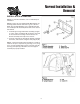
Normal Installation & Removal INSTALLATION & REMOVAL NOTE: For first-time installation, refer to Initial Setup & Installation. NOTE: If mower deck is equipped with Mulching Kit, the mulching baffles must be removed for grass collection. Make sure the high-lift blades (34') or high-lift tabs (30') are installed per the Assembly Instructions at the back of this manual. 1. Install the grass bag and bracket assembly (A, figure 1) on the anchor assemblies (B) located on each side of the transmission housing.
Normal Installation & Removal Figure 3. A. Grass Bag Frame B. Support Bracket Figure 4. (30” Mower Shown) A. Adapter B. Wing Nut C. Deflector D. Jam nut, 5/16-18 E. 1/2” Hole 3. Open grass bag cover and install grass bag frames (A, figure 3) to support brackets (B). 4. On 30" mower, lift the deflector (C) up and install the adapter (A, figure 4) to mower deck by hooking bracket over the rear carriage bolt and securing with jam nut (D) and positioning front slot on the adapter under wing nut (B).
Troubleshooting The following table provides troubleshooting instructions for the more common and easily corrected problems. For problems not covered in the table, see your dealer. WARNING To avoid serious Injury, perform maintenance on the grass catcher only after stopping the engine and waiting for all moving parts to come to a complete stop. Always remove the ignition key before beginning the maintenance to prevent accidental starting of the engine.
Initial Setup & Assembly 30” MODELS BLADE AND ADAPTER ASSEMBLY Blade Assembly - 30” Mower 1. Remove the mower deck to access the blade or using an overhead hoist, elevate the front of the unit to access the mower blade. 2. Mount the lifts (B, Figure 6) to the discharge side of the blade as shown. Torque nuts to 14 ft. lbs. Adapter & Mounting Hardware Installation 30” Mower D C 1.
Initial Setup - 30” Models E A C D E 1/4" B Drill 1/2" Hole 1" Figure 8. A. Carriage Bolt, 5/16-18 x 2-1/4 B. Cup C. Whiz Flange Nut, 5/16 D. Wing Nut E. Centerlock Nut, 5/16 E Figure 9. (30” Mower Shown) A. Adapter B. Wing Nut C. Deflector D. Jam nut, 5/16-18 E. 1/2” Hole 3. Install 5/16-18 x 2-1/4 carriage bolt (A, figure 8) through front hole in mower deck along with cup (B), whiz flange nut (C), wing nut (D) and center lock nut (E).
Initial Setup - 34” Models 34" MODELS BAFFLE, BLADE, & ADAPTER ASSEMBLY E I D H K G B H Install Baffle F C 1. Remove mower deck from rider. Position mower deck upright and support in this position. J A 2. Position baffle with notched end towards discharge side opening, Install all hardware as shown in figure 10. The notch must be positioned to clear the stone guard weldment. M L 3.
Initial Setup - 34” Models Install Blades Early Models with Splined Arbor 1. Remove existing discharge-side blade but retain hardware. Remove the retaining band (E, figure 11 b) from the arbor shaft and remove the existing splined adapter (3-3/8" O.D. F, figure 11b). This adapter can be discarded. The new 2" O.D. splined adapter supplied with the bagger can be used with regular or high-lift blades. Install the new 2" splined adapter with existing retaining band (E). 2.
Initial Setup - All Models FRAME & BAGGER SUPPORT ASSEMBLY - ALL MODELS H Note: Units with 0510 transmissions use anchors (A, figure 13) with a notch, all other units use anchor with no notch. See Inset Figure 13. D F 1. Assemble the two anchors (A, figure 13) to the transmission housing using the 5/16-18 x 3 capscrews (B), washers (C) and nuts (E). Install the capscrews from the bottom of transmission. Do not tighten hardware at this time. E A 2.
Initial Setup - All Models GRASS CATCHER ASSEMBLY ALL MODELS NOTE: Cover and bag support are packaged as an assembly with long clevis pins and clips. It may be easier to separate components for the following step. 1. Install horizontal bag support (A, figure 14) to upright catcher support (B) holes as shown. Note that the open set of holes (D) is toward the discharge side of mower. Install four 3/8-16 x 7/8 capscrews (C) from the front and lightly secure with flange lock nuts. 2.
Initial Setup - All Models 5. Open cover and fasten cable (A, figure 17) to tube support (B) to prevent cover from going over center when opened. Loop end of cable fits over washer (C). Figure 17. A. Cable B. Support C. Washer 6. Open grass bag cover and install grass bag frames (A, figure 18) to support brackets (B). Make sure cover handle latches to grass bag frames. Figure 18. A. Grass Bag Frame B.
Initial Setup - All Models 7. Apply dry talc powder to rubber seal at cover opening. Install tube (A, figure 19) as far as possible into opening to clear adapter and install over adapter. Figure 19. A. Tube B. Wire Form Location 8. Secure tube by moving wire form (A, figure 20) down over round cup (B) on adapter surface. Figure 20. A. Wire Form B.
Installation Instructions Baffle Kit Part No. 1686783 For Coronet / 400 / 2400 Series Riders D A C B Figure 1. Installation This kit adds a baffle to twin bag grass catchers installed on Coronet / 400 / 2400 series riders. Kit Contents: Part No. 1720375 Qty. 1 Description Baffle INSTALLATION WARNING Before beginning any service work turn off the PTO, set the parking brake, turn off the ignition, and disconnect the spark plug wire(s). 1.
EXHAUST SHIELD KIT MFG. NO. 1666610 INSTALLATION INSTRUCTIONS 1. Raise the seat deck to expose the right-hand top duct. 2. See figure 1. Cut out the template below and place it on the duct with the edges aligned. Tape the template in place and drill out the holes as indicated using a 13/W drill bit. Figure 1. Placing Template for drilling holes 3. See figure 2. Install the front exhaust shield and rear exhaust shield using the hardware supplied with the kit. Tighten securely. Figure 2.
Hardware Identification & Torque Specifications Common Hardware Types Torque Specification Chart Hex Head Capscrew FOR STANDARD MACHINE HARDWARE (Tolerance ± 20%) Washer Hardware Grade Lockwasher Carriage Bolt No Marks SAE Grade 2 Hex Nut Size Of Hardware Standard Hardware Sizing 8-32 8-36 10-24 10-32 1/4-20 1/4-28 5/16-18 5/16-24 3/8-16 3/8-24 7/16-14 7/16-20 1/2-13 1/2-20 9/16-12 9/16-18 5/8-11 5/8-18 3/4-10 3/4-16 7/8-9 7/8-14 1-8 1-12 When a washer or nut is identified as 1/2”, this is the