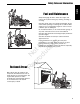
N ep o ro t fo du r ct io n OPERATOR’S MANUAL Cobalt Series 27HP Zero-Turn Riders Description 2690479 Simplicity 27HP Cobalt Zero-Turn Rider with 61” Mower R Mfg. No. 5100724 Revision B Rev.
Thank you for purchasing this quality-built Simplicity product. We’re pleased that you’ve placed your confidence in the Simplicity brand. When operated and maintained according to the instructions in this manual, your Simplicity product will provide many years of dependable service. This manual contains safety information to make you aware of the hazards and risks associated with this machine and how to avoid them.
Table of Contents Safety Safety Rules & Information ................................2 Identification Numbers .....................................11 Safety Decals .....................................................12 Safety Icons & Interlock System......................13 Features & Controls ..........................................14 Control Functions..................................................14 Operation ...........................................................
Safety Rules and Information Safety Operating Safety Congratulations on purchasing a superior-quality piece of lawn and garden equipment. Our products are designed and manufactured to meet or exceed all industry standards for safety. Do not operate this machine unless you have been trained. Reading and understanding this operator’s manual is a way to train yourself. Power equipment is only as safe as the operator.
Safety Rules and Information Operation on slopes can be dangerous. Using the unit on a slope that is too steep where you do not have adequate wheel traction (and control) can cause sliding, loss of steering, control, and possible rollover. You should not operate on a slope greater than a 5.4 foot rise over a 20 foot length (15 degrees). Always mow across slopes, not up and down (to maintain traction on the wheels) and avoid sudden turns or rapid speed changes.
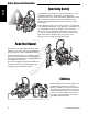
Safety Safety Rules and Information Roll Bar Use Keep the roll bar in the raised position and fasten the seat belt. There is no roll over protection when the roll bar is down! Do not jump off if the mower tips (it is safer to be secured by the seat belt with the roll bar raised.) N ep o ro t fo du r ct io n Lower the roll bar only when necessary (such as to temporarily clear a low overhanging obstacle) and NEVER remove it. Do NOT use the seat belt when the roll bar is down.
Safety Rules and Information Safety Fuel and Maintenance Always disengage all drives, shutoff the engine, and remove the key before doing any cleaning, refueling, or servicing. Gasoline and its vapors are extremely flammable. Do not smoke while operating or refueling. Do not add fuel while engine is hot or running. Allow engine to cool for at least 3 minutes prior to adding fuel. Do not add fuel indoors, in an enclosed trailer, garage, or any other enclosed area that is not well ventilated.
Safety Rules and Information Safety Read these safety rules and follow them closely. Failure to obey these rules could result in loss of control of unit, severe personal injury or death to you, or bystanders, or damage to property or equipment. This mowing deck is capable of amputating hands and feet and throwing objects. The triangle in text signifies important cautions or warnings which must be followed. GENERAL OPERATION R N ep o ro t fo du r ct io n 1.
Safety Rules and Information SLOPE OPERATION WARNING Safety Never operate on slopes greater than 15°. Select slow ground speed before driving onto slope. Use extra caution when operating on slopes with rear-mounted grass catchers. Mow across the face of slopes, not up and down,use caution when changing directions and DO NOT START OR STOP ON SLOPE. TOWED EQUIPMENT (RIDE-ON UNITS) 1. Tow only with a machine that has a hitch designed for towing. Do not attach towed equipment except at the hitch point. 2.
Safety Rules and Information fuel line clamps further than necessary. Ensure clamps grip hoses firmly over the filter after installation. 12. Do not use gasoline containing METHANOL, gasohol containing more than 10% ETHANOL, gasoline additives, or white gas because engine/fuel system damage could result. 13. If the fuel tank must be drained, it should be drained outdoors. 14. Replace faulty silencers/mufflers. 15. Maintain or replace safety and instruction labels as necessary. 16.
Safety Rules & Information ROLL BAR INSTRUCTIONS WARNING In order to avoid serious injury or death from roll over, it is important to follow the warnings listed below. WARNING 2) Make sure there isn’t any missing, damaged, or loose mounting hardware. 3) Make sure the ROLL BAR has been correctly and completely installed. • EVERY 100 HOURS - Inspect the ROLL BAR structure and mounting hardware for: 1) Any cracks in the structure (structural members and/or welds).
INSPECT BUCKLE & LATCH WARNING Failure to properly inspect and maintain the seat belt can cause serious injury or death. INSPECTION AND MAINTENANCE OF THE ROLL BAR SEAT BELT • The seat belt like the ROLL BAR, needs to be periodically inspected to verify that the integrity has not been compromised through normal machine use, misuse, age degradation, modifications, or a roll over. If the seat belt does not pass all of the following tests, it should be replaced.
Identification Numbers SA North American Models M PL E SA Mfg. No.: Safety Identification Numbers 169XXXX M Serial No.: XXXXX kW: XX Engine RPM XXXX LpA: XXX dB(A) Vibration @ Wheel: XXX m/s² Vibration @ Seat: XXX m/s² XXXX dB(A) Identification Tag CE Models PL E Simplicity Mfg. Inc. Port Washington, WI USA 53074-0997 XXXXXXX When contacting your authorized dealer for replacement parts, service, or information you MUST have these numbers.
Safety Decals This unit has been designed and manufactured to provide you with the safety and reliability you would expect from an industry leader in outdoor power equipment manufacturing. All DANGER, WARNING, CAUTION and instructional messages on your rider and mower should be carefully read and obeyed. Personal bodily injury can result when these instructions are not followed. The information is for your safety and it is important! The safety decals below are on your rider and mower.
Safety Interlock System Safety Icons This unit is equipped with safety interlock switches. These safety systems are present for your safety, do not attempt to bypass safety switches, and never tamper with safety devices. Check their operation regularly. Operational SAFETY Checks Test 1 — Engine should NOT crank if: • PTO switch is engaged, OR • Parking brake is not engaged, OR • Motion control handles are not in the NEUTRAL position.
N ep o ro t fo du r ct io n Controls Features & Controls CONTROL FUNCTIONS The information below briefly describes the function of individual controls. Starting, stopping, driving, and mowing require the combined use of several controls applied in specific sequences. To learn what combination and sequence of controls to use for various tasks see the OPERATION section. R Deck Lift Pedal, Cutting Height Adjustment Pin & Deck Lift Lock Lever These control the cutting height of the mower deck.
Features & Controls Ignition Switch Fuel Tank Cap The ignition switch starts and stops the engine, it has three positions: OFF Fuel Level Gauge Displays the fuel level in the tank. Headlight The headlight switch turns the headlights on and off. Throttle Control The throttle controls engine speed. Move the throttle forward to increase engine speed and back to decrease engine speed. Always operate at FULL throttle.
Operation GENERAL OPERATING SAFETY Before first time operation: • Be sure to read all information in the Safety and Operation sections before attempting to operate this tractor and mower. • Become familiar with all of the controls and how to stop the unit. • Drive in an open area without mowing to become accustomed to the unit. CHECKS BEFORE STARTING • Check that crankcase is filled to full mark on dipstick. See the engine Operator’s Manual for instructions and oil recommendations.
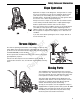
Operation PUSHING THE RIDER BY HAND WARNING If you do not understand how a specific control functions, or have not yet thoroughly read the FEATURES & CONTROLS section, do so now. Do NOT attempt to operate the tractor without first becoming familiar with the location and function of ALL controls. STARTING THE ENGINE Towing the unit will cause hydraulic pump and wheel motor damage. Do not use another vehicle to push or pull this unit. N ep o ro t fo du r ct io n 1.
Operation ZERO TURN DRIVING PRACTICE The lever controls of the Zero Turn rider are responsive, and learning to gain a smooth and efficient control of the rider’s forward, reverse, and turning movements will take some practice. Locate a smooth, flat area of your lawn — one with plenty of room to maneuver. (Clear the area of objects, people and animals before you begin.
Operation Practice Turning Around a Corner Practice Turning In Place While traveling forward allow one handle to gradually return back toward neutral. Repeat several times. To turn in place, “Zero Turn,” gradually move one ground speed control lever forward from neutral and one lever back from neutral simultaneously. Repeat several times. NOTE: To prevent pivoting directly on the tire tread, it is best to keep both wheels going at least slightly forward.
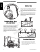
Operation RAISE & LOWER THE ROLL BAR C WARNING AVOID SERIOUS INJURY OR DEATH FROM ROLL OVER: Keep roll bar in the raised position and use seat belt. THERE IS NO ROLL OVER PROTECTION WHEN THE ROLL BAR IS DOWN Lower the roll bar only when necessary and NEVER remove it. Do NOT use seat belt when the roll bar is down. Raise the roll bar as soon as clearance permits. Do NOT jump off if mower tips. D C A B D To raise the roll bar: Figure 9. Raise & Lower the Roll Bar A. Hair Pin Clip B. Retainer Pin C.
Operation MOWING Before mowing, set the cutting height as described in the Troubleshooting, Adjustments & Service section. 1. Engage the parking brake. Make sure the PTO switch is disengaged and the motion control lever is in the NEUTRAL position. 2. Start the engine (see STARTING THE ENGINE). 3. Set the throttle to FULL. 4. Engage the PTO by pulling up on the PTO switch (E, Figure 1). 5. Begin mowing. See Mowing Recommendations section for tips on mowing patterns and lawn care.
Operation When and How Often to Mow The time of day and condition of the grass greatly affect the results you’ll get when mowing. For the best results, follow these guidelines: 1. Mow when the grass is between three and five inches high. 2. Mow with sharp blades. Short clippings of grass one inch or shorter decompose more quickly than longer blades. Sharp mower blades cut grass cleanly and efficiently, preventing frayed edges which harm the grass. 3. Mow at time of day when the grass is cool and dry.
Operation Proper Mulching ATTACHING A TRAILER Mulching consists of a mower deck which cuts and recuts clippings into tiny particles and which then blows them down INTO the lawn. These tiny particles decompose rapidly into by-products your lawn can use. UNDER PROPER CONDITIONS, your mulching mower will virtually eliminate noticeable clippings on the lawn surface. The maximum weight of a towed trailer should be less than 200 lbs (91kg).
Regular Maintenance MAINTENANCE SCHEDULE The following schedule should be followed for normal care of your rider and mower. You will need to keep a record of your operating time. Determining operating time is easily accomplished by observing the elapsed time recorded by the hour meter.
Regular Maintenance CHECK TIRE PRESSURES Tire pressure should be checked periodically, and maintained at the levels shown in the chart. Note that these pressures may differ slightly from the “Max Inflation” stamped on the side-wall of the tires. The pressures shown provide proper traction, improve cut quality, and extend tire life. Tire Pressure Front 25 psi (1,72 bar) Rear 15 psi (1,03 bar) CHECKING / ADDING FUEL WARNING To add fuel: 1. Stop the engine and allow to cool for at least 3 minutes. 2.
Regular Maintenance CHECK HYDRAULIC OIL LEVEL 1. Before removing the reservoir cap, make sure the area around the reservoir cap and fill neck of the reservoir is free of dust, dirt, or other debris. 2. Unscrew the reservoir cap (B, Figure 16). 3. Look down the filler neck of the hydraulic oil reservoir (A, Figure 16) and observe the oil level. When cold, the oil level should be approximately 4” (10 cm) below top of the filler neck. 4.
Regular Maintenance LUBRICATION Lubricate the unit at the locations shown in Figures 18 through 22 as well as the following lubrication points. Grease: • • • • front caster wheel axles & yokes deck lift pivot blocks mower deck spindles mower deck idler arm Use grease fittings when present. Disassemble parts to apply grease to moving parts when grease fittings are not installed. Figure 19. Control Handle Pivots & Seat Plate Pivots Not all greases are compatible. Use automotive-type lithium grease.
Regular Maintenance BATTERY MAINTENANCE D NOTE: This unit is equipped with a maintenance-free BCIU1 battery. C Cleaning the Battery and Cables 1. Remove the hydraulic oil reservoir mounting hardware (C, Figure 23) and move the reservoir (D) forward to expose the battery. 2. Disconnect the cables from the battery, negative (black) cable first (B). 3. Clean the battery terminals and cable ends with a wire brush until shiny. 4.
Regular Maintenance SERVICING THE MOWER BLADES WARNING Figure 24. Removing the Blade N ep o ro t fo du r ct io n 1. Blades should be sharp and free of nicks and dents. If not, sharpen blades as described in the following steps. 2. To remove blade for sharpening, use a 1” wrench on the flats of the spindle shaft while removing the blade mounting bolt with a 15/16” wrench (Figure 24). 3. Use a file to sharpen blade to fine edge. Remove all nicks and dents in blade edge.
Troubleshooting, Adjustment & Service TROUBLESHOOTING While normal care and regular maintenance will extend the life of your equipment, prolonged or constant use may eventually require that service be performed to allow it to continue operating properly. The troubleshooting guide below lists the most common problems, their causes and remedies. See the information on the following pages for instructions on how to perform most of these minor adjustments and service repairs yourself.
Troubleshooting, Adjustment & Service Rider Troubleshooting Continued. PROBLEM CAUSE REMEDY Engine runs, but rider will not drive. 1. Hydraulic release valve(s) in “open” position. 2. Belt is broken. 3. Drive belt slips. 4. Brake is not fully released. 1. Pulleys or belt greasy or oily. 2. Tension too loose. 1. Turn valve(s) clockwise to close. Rider drive belt slips. Brake will not hold. Rider steers or handles poorly. 3. 1. 2. 1. 2. Belt stretched or worn. Brake is incorrectly adjusted.
Troubleshooting, Adjustment & Service TROUBLESHOOTING COMMON CUTTING PROBLEMS PROBLEM CAUSE REMEDY Streaking. 1. 2. 3. 4. 5. 6. 1. Sharpen your blades. 2. Replace your blades. 3. Always mow at full throttle. 4. Slow down. 5. Clean out the mower. 6. Overlap your cutting rows. 3. 4. 5. Blades are not sharp. Blades are worn down to far. Engine speed is too slow. Ground speed is too fast. Deck is plugged with grass Not overlapping cutting rows enough. Not overlapping enough when turning.
Troubleshooting, Adjustment & Service SEAT ADJUSTMENT A See Figure 27. The seat can be adjusted forward and back. Move the lever (A) forward, position the seat as desired, and release the lever to lock the seat into position. GROUND SPEED CONTROL LEVER ADJUSTMENT The control levers can be adjusted in three ways. The alignment of the control levers, the placement of the levers (how close the ends are to one another) and the height of the levers can be adjusted. Figure 27. Seat Adjustment A.
Troubleshooting, Adjustment & Service NEUTRAL ADJUSTMENT If the tractor “creeps” while the ground speed control levers are locked in NEUTRAL, then it may be necessary to adjust the linkage rod. NOTE: Perform this adjustment on a hard, level surface such as a concrete floor. B D A Figure 30. Neutral Adjustment (RH side shown) A. Adjustment Linkage Rod B. Jam Nut C. Ball Joint D. Locking Nuts N ep o ro t fo du r ct io n 1. Disengage the PTO, engage the parking brake and turn off the engine. 2.
Troubleshooting, Adjustment & Service PARKING BRAKE ADJUSTMENT 1. Disengage the PTO, engage the parking brake, stop the engine and remove the ignition key. 2. Raise the seat plate. 3. Locate the brake spring (A, Figure 32). 4. With the parking brake engaged, measure the compressed spring length. The spring should be 1-15/16” - 2” (4,9 - 5,1 cm) when compressed. 5. If the spring is not within this range, release the parking brake and turn the adjustment nut (B) to compress or relax the spring. 6.
Troubleshooting, Adjustment & Service SUSPENSION ADJUSTMENT The shock assembly can be adjusted to vary the amount of pre-load applied to the springs. This allows the operator to maintain the ride height. Use less pre-load for light weight operators. Use more pre-load for heavy weight operators. To adjust the spring pre-load: WARNING Use two hands when adjusting the shock springs. This will prevent the wrench from slipping while pressure is being applied. 4.
Troubleshooting, Adjustment & Service MOWING HEIGHT ADJUSTMENT The cutting height adjustment pin (A, Figure 34) controls the mower cutting height. The cutting height is adjustable between 1-3/4” (4,4 cm) and 5” (12,7 cm) in 1/4” (0,64 cm) increments. 1. Depress the deck lift foot pedal (B) until it locks into the 5” (12,7 cm) position. 2. Place the cutting height adjustment pin in the desired cutting height. 3.
Troubleshooting, Adjustment & Service DECK LIFT ROD TIMING ADJUSTMENT Inner Rod 1. Park machine on a flat, level surface. Disengage the PTO, stop the engine and engage the parking brake. Rear tires must be inflated to 18 psi (1,24 bar); front tires to 25 psi (1,72 bar). nd e2 r su a Me t re u as 1s Me 2. To check the inner lift rod timing, measure and record the distance between the inner lift pivots and the inner rod pivots. Repeat for other side of unit. See Figure 36. 3.
Troubleshooting, Adjustment & Service DECK LEVELING ADJUSTMENT A NOTE: Before adjusting the deck level, the deck lift rod timing must be checked and/or adjusted. Figure 39. 2 x 4 Locations A. 1/4” Spacers Adjust Here N ep o ro t fo du r ct io n 1. Park machine on a flat, level surface. Disengage the PTO, stop the engine and engage the parking brake. Rear tires must be inflated to 15 psi (1,03 bar); front tires to 25 psi (1,72 bar). 2. Lock the deck lift pedal in the 5” (12,7cm) position.
Troubleshooting, Adjustment & Service HYDRAULIC PUMP DRIVE BELT REPLACEMENT A D 8 3/8” (21,2 cm) E C C F G Figure 42. Hydraulic Pump Drive Belt Replacement A. Pump Drive Belt B. Crankshaft Pulley C. Pump Pulley D. Idler Pulley E. Idler Arm F. Spring G. Spring Anchor Hook R Troubleshooting N ep o ro t fo du r ct io n 1. Park the tractor on a smooth, level surface such as a concrete floor. Disengage the PTO, engage the parking brake, turn off the engine, and remove the ignition key. 2.
Troubleshooting, Adjustment & Service MOWER BELT REPLACEMENT A B To avoid damaging belts, DO NOT PRY BELTS OVER PULLEYS. WARNING C Figure 43. Mower PTO Belt A. Idler Arm B. Stationary Idler Pulley C. 1/2” Breaker Bar D. Spring N ep o ro t fo du r ct io n 1. Park the tractor on a smooth, level surface such as a concrete floor. Disengage the PTO, engage the parking brake, turn off the engine, and remove the ignition key. 2.
Troubleshooting, Adjustment & Service BATTERY CHARGING A dead battery or one too weak to start the engine may be the result of a defect in the charging system or other electrical component. If there is any doubt about the cause of the problem, see your dealer. If you need to replace the battery, follow the steps under Cleaning the Battery & Cables in the Regular maintenance Section.
Specifications NOTE: Specifications are correct at time of printing and are subject to change without notice. * Actual sustained equipment horsepower will likely be lower due to operating limitations and environmental factors. ENGINE: TRANSMISSIONS: 27 HP* Kohler Make Model Horsepower Displacement Electrical System Oil Capacity HydroGear PG-3H / HGM-12E 3131 Kohler CV740S 27 @ 3600 rpm 44.24 Cu. in (725 cc) 12 Volt, 16 amp. Alternator, Battery: 340 CCA 4.2 pt. (2.
R N ep o ro t fo du r ct io n Notes 44 www.simplicitymfg.
N ep o ro t fo du r ct io n R
Product Quick Specs: ENGINE: TRANSMISSIONS: 27 HP* Kohler Make Model Horsepower Displacement Electrical System Oil Capacity HydroGear PG-3H / HGM-12E 3131 Kohler CV740S 27 @ 3600 rpm 44.24 Cu. in (725 cc) 12 Volt, 16 amp. Alternator, Battery: 340 CCA 4.2 pt. (2.0 L) w/ Filter CHASSIS: Front Wheels Capacity: 11 Gallons (41.6 L) Total Tire Size: 22 x 11.00 -10 Inflation Pressure: 15 psi (1,03 bar) Tire Size: 13 x 5.