OPERATOR’S MANUAL Cobalt Series 30HP Zero-Turn Riders Mfg. No. Description 5900763 Simplicity 30HP Cobalt Zero-Turn Rider with 61” Mower 5101064 Revision IR Rev.
Thank you for purchasing this quality-built Simplicity product. We’re pleased that you’ve placed your confidence in the Simplicity brand. When operated and maintained according to the instructions in this manual, your Simplicity product will provide many years of dependable service. This manual contains safety information to make you aware of the hazards and risks associated with this machine and how to avoid them.
Table of Contents Operator Safety ..............................................2 Safety Safety Rules & Information ..............................................2 Safety Decals ..................................................................11 Safety Icons & Interlock System ....................................12 Features & Controls ....................................... 13 Identification Numbers ...................................................13 Control Functions .................................
Operator Safety Safety Operator Safety Operating Safety Read the Manual The operator’s manual contains important safety information you need to be aware of BEFORE you operate your unit as well as DURING operation. Safe operating techniques, an explanation of the product’s features and controls, and maintenance information is included to help you get the most out of your equipment investment. Be sure to completely read the Safety Rules and Information found on the following pages.
Operator Safety Slope Operation Safety Operation on slopes can be dangerous. Using the unit on a slope that is too steep where you do not have adequate wheel traction (and control) can cause sliding, loss of steering, control, and possible rollover. You should not operate on a slope greater than a 5.4 foot rise over a 20 foot length (15 degrees). Controls Always mow across slopes, not up and down (to maintain traction on the wheels) and avoid sudden turns or rapid speed changes.
Safety Operator Safety Roll Bar Use Keep the roll bar in the raised position and fasten the seat belt. There is no roll over protection when the roll bar is down! Do not jump off if the mower tips (it is safer to be secured by the seat belt with the roll bar raised.) Controls Lower the roll bar only when necessary (such as to temporarily clear a low overhanging obstacle) and NEVER remove it. Do NOT use the seat belt when the roll bar is down. Raise the roll bar as soon as clearance permits.
Operator Safety Safety Fuel and Maintenance Controls Always disengage all drives, shutoff the engine, and remove the key before doing any cleaning, refueling, or servicing. Gasoline and its vapors are extremely flammable. Do not smoke while operating or refueling. Do not add fuel while engine is hot or running. Allow engine to cool for at least 3 minutes prior to adding fuel. Do not add fuel indoors, in an enclosed trailer, garage, or any other enclosed area that is not well ventilated.
Operator Safety Safety Read these safety rules and follow them closely. Failure to obey these rules could result in loss of control of unit, severe personal injury or death to you, or bystanders, or damage to property or equipment. This mowing deck is capable of amputating hands and feet and throwing objects. The triangle in text signifies important cautions or warnings which must be followed. Troubleshooting Maintenance Operation Controls General Operation 1.
Operator Safety Slope Operation 1. Tow only with a machine that has a hitch designed for towing. Do not attach towed equipment except at the hitch point. 2. Follow the manufacturer’s recommendations for weight limit for towed equipment and towing on slopes. See attaching a trailer under OPERATION. 3. Never allow children or others in or on towed equipment. 4. On slopes, the weight of the towed equipment may cause loss of traction and loss of control. 5. Travel slowly and allow extra distance to stop. 6.
Operator Safety Specifications Troubleshooting Maintenance Operation Controls Safety Service and Maintenance Safe Handling of Gasoline 1. Extinguish all cigarettes, cigars, pipes, and other sources of ignition. 2. Use only approved gasoline containers. 3. Never remove the gas cap or add fuel with the engine running. Allow the engine to cool before refueling. 4. Never fuel the machine indoors. 5.
Operator Safety Roll Bar Instructions WARNING In order to avoid serious injury or death from roll over, it is important to follow the warnings listed below. WARNING A ROLL BAR, like any other safety device, needs to be periodically inspected to verify that the integrity of the device has not been compromised through normal machine use, misuse, age degradation, modifications, or a roll over. 1) Any cracks in the structure (structural members and/ or welds).
Safety Operator Safety Inspection and Maintenance of the Roll Bar Seat Belt INSPECT BUCKLE & LATCH WARNING Controls Failure to properly inspect and maintain the seat belt can cause serious injury or death. • The seat belt like the ROLL BAR, needs to be periodically inspected to verify that the integrity has not been compromised through normal machine use, misuse, age degradation, modifications, or a roll over. If the seat belt does not pass all of the following tests, it should be replaced.
Operator Safety Safety Decals Although reading this manual and the safety instructions it contains will provide you with the necessary basic knowledge to operate this equipment safely and effectively, we have placed several safety labels on the unit to remind you of this important information while you are operating your unit. 1 2 If any of these decals are lost or damaged, replace them at once. See your local dealer for replacements.
Operator Safety Safety Safety Icons Safety Interlock System This unit is equipped with safety interlock switches. These safety systems are present for your safety, do not attempt to bypass safety switches, and never tamper with safety devices. Check their operation regularly. The alert symbol ( ) is used to identity safety information about hazards that can result in personal injury.
Features and Controls Features and Controls Safety Identification Numbers M SA PL North American Models E Controls M SA Mfg. No.: 169XXXX XXXX dB(A) CE Models Identification Tag PL Serial No.: XXXXX kW: XX Engine RPM XXXX LpA: XXX dB(A) Vibration @ Wheel: XXX m/s² Vibration @ Seat: XXX m/s² E Simplicity Mfg. Inc. Port Washington, WI USA 53074-0997 XXXXXXX Operation When contacting your authorized dealer for replacement parts, service, or information you MUST have these numbers.
Specifications Troubleshooting Maintenance Operation Controls Safety Features and Controls Control Functions The information below briefly describes the function of individual controls. Starting, stopping, driving, and mowing require the combined use of several controls applied in specific sequences. To learn what combination and sequence of controls to use for various tasks see the OPERATION section.
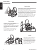
Features and Controls Ignition Switch OFF Stops the engine and shuts off the electrical system. RUN Allows the engine to run and powers the electrical system. The seat can be adjusted forward and back. Move the lever towards the left, position the seat as desired, and release the lever to lock the seat in position. Safety The ignition switch starts and stops the engine, it has three positions: Seat Adjustment Lever Fuel Tank Cap To remove the cap, turn counterclockwise.
Operation Controls Safety Operation General Operating Safety Before first time operation: • Be sure to read all information in the Safety and Operation sections before attempting to operate this tractor and mower. • Become familiar with all of the controls and how to stop the unit. • Drive in an open area without mowing to become accustomed to the unit. Checks Before Starting • Check that crankcase is filled to full mark on dipstick (B, Figure 1).
Operation Check Tire Pressures Pressure 25 psi (1,72 bar) Rear 15 psi (1,03 bar) Controls Tire Front Safety Tire pressure should be checked periodically, and maintained at the levels shown in the chart. Note that these pressures may differ slightly from the “Max Inflation” stamped on the side-wall of the tires. The pressures shown provide proper traction, improve cut quality, and extend tire life. Figure 2. Checking Tire Pressure Seat Adjustment A See Figure 3.
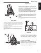
Operation Controls Safety Mowing Height Adjustment The cutting height adjustment pin (A, Figure 5) controls the mower cutting height. The cutting height is adjustable between 1-3/4” (4,4 cm) and 5” (12,7 cm) in 1/4” (0,64 cm) increments. 1. Depress the deck lift foot pedal (B) until it locks into the 5” (12,7 cm) position. 2. Place the cutting height adjustment pin in the desired cutting height. 3. Depress the deck lift foot pedal then push the lock lever (C) towards the right to release the lock. 4.
Operation WARNING Safety Read the Operator’s Manual before attempting to operate the machine. Stopping the Rider 1. While sitting in the operator’s seat, engage the parking brake and make sure the PTO switch is disengaged and the motion control handles are locked in the NEUTRAL position. 2. NOTE: A warm engine may not require choking. Set the engine throttle control to FAST throttle position. Then fully close the choke by pulling the knob OUT fully. 3.
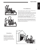
Operation Safety Zero-Turn Driving Practice The lever controls of the Zero Turn rider are responsive, and learning to gain a smooth and efficient control of the rider’s forward, reverse, and turning movements will take some practice. Operation Controls Spending some time going through the maneuvers shown and becoming familiar with how the unit accelerates, travels, and steers — before you begin mowing —is absolutely essential to getting the most out of the Zero Turn rider.
Operation Practice Turning In Place While traveling forward allow one handle to gradually return back toward neutral. Repeat several times. To turn in place, “Zero Turn,” gradually move one ground speed control lever forward from neutral and one lever back from neutral simultaneously. Repeat several times. NOTE: To prevent pivoting directly on the tire tread, it is best to keep both wheels going at least slightly forward.
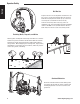
Operation Controls Safety Raise and Lower the Roll Bar WARNING Avoid serious injury or death from roll over. D C • Keep the roll bar in the raised position and use seat belt. • There is no roll over protection when the roll bar is down. • Lower the roll bar only when necessary and NEVER remove it. • Do NOT use the seat belt when the roll bar is down. • Raise the roll bar as soon as clearance permits. • Do NOT jump off if mower tips. To Lower the Roll Bar: Operation C 1.
Operation Mowing Safety Before mowing, set the cutting height as described in the Operation section. 1. Engage the parking brake. Make sure the PTO switch is disengaged and the ground speed control levers are in the NEUTRAL position. 2. Start the engine (see Starting the Engine). 3. Set the throttle to FULL. Controls 4. Engage the PTO by pulling up on the PTO switch (E, Figure 1). Figure 14. Proper Cutting Height 6. When finished, shut off the PTO. Tall Grass Requires Incremental Cutting 7.
Operation Safety When and How Often to Mow The time of day and condition of the grass greatly affect the results you’ll get when mowing. For the best results, follow these guidelines: Controls 1. Mow when the grass is between three and five inches high. 2. Mow with sharp blades. Short clippings of grass one inch or shorter decompose more quickly than longer blades. Sharp mower blades cut grass cleanly and efficiently, preventing frayed edges which harm the grass. 3.
Operation Attaching a Trailer Mulching consists of a mower deck which cuts and recuts clippings into tiny particles and which then blows them down INTO the lawn. These tiny particles decompose rapidly into by-products your lawn can use. UNDER PROPER CONDITIONS, your mulching mower will virtually eliminate noticeable clippings on the lawn surface. The maximum weight of a towed trailer should be less than 200 lbs (91kg). Secure the trailer with a appropriately sized clevis pin (A, Figure 17) and clip (B).
Regular Maintenance Safety Regular Maintenance Maintenance Schedule The following schedule should be followed for normal care of your rider and mower. You will need to keep a record of your operating time. Determining operating time is easily accomplished by observing the elapsed time recorded by the hour meter.
Regular Maintenance Checking / Adding Fuel WARNING Safety To add fuel: 1. Stop the engine and allow to cool for at least 3 minutes. 2. Remove the fuel cap (see Figure 1). 3. Fill the tank to the bottom of the filler neck. This will allow for fuel expansion. NOTE: Do not overfill. Refer to your engine manual for specific fuel recommendations.
Regular Maintenance Controls Safety Check Hydraulic Oil Level 1. Before removing the reservoir cap, make sure the area around the reservoir cap and fill neck of the reservoir is free of dust, dirt, or other debris. 2. Unscrew the reservoir cap (B, Figure 19). 3. Look down the filler neck of the hydraulic oil reservoir (A) and observe the oil level. When cold, the oil level should be approximately 4” (10 cm) below top of the filler neck. 4.
Regular Maintenance Lubrication Safety Lubricate the unit at the locations shown in Figures 21 through 25 as well as the following lubrication points. Grease: • front caster wheel axles & yokes • deck lift pivot blocks • mower deck spindles • mower deck idler arm Controls Use grease fittings when present. Disassemble parts to apply grease to moving parts when grease fittings are not installed. Figure 22. Control Handle Pivots & Seat Plate Pivots Not all greases are compatible.
Regular Maintenance Safety Servicing The Mower Blades Removing the Mower Blade WARNING Controls Avoid injury! Mower blades are sharp. Always wear gloves when handling mower blades or working near blades. 1. Wedge a wooden block between the mower blade and the mower deck housing to keep the mower blade from turning. 2. To remove the mower blade, use a 15/16” wrench to remove the mower blade mounting bolt (Figure 26). Figure 26.
Regular Maintenance Sharpening the Mower Blade A Safety WARNING Avoid injury! Mower blades are sharp. • Always wear gloves when handling mower blades or working near blades. • Always wear safety eye protection when grinding. Figure 29. Sharpening the Mower Blade A. Mower Blade Bevel B. Mower Blade Cutting Edge Controls Operation 1. Sharpen the mower blades with grinder, hand file, or electric blade sharpener. 2.
Regular Maintenance Controls Safety Battery Charging A dead battery or one too weak to start the engine may be the result of a defect in the charging system or other electrical component. If there is any doubt about the cause of the problem, see your dealer. If you need to replace the battery, follow the steps under Cleaning the Battery & Cables in the Regular Maintenance section.
Regular Maintenance Ground Speed Control Lever Adjustment Safety The control levers can be adjusted in three ways. The alignment of the control levers, the placement of the levers (how close the ends are to one another) and the height of the levers can be adjusted. A B To Adjust the Handle Alignment Loosen the mount bolts (A, Figure 33) and pivot the lever(s) (C) to align with each other.
Regular Maintenance Safety Neutral Adjustment If the tractor “creeps” while the ground speed control levers are locked in NEUTRAL, then it may be necessary to adjust the linkage rod. 1. Park the machine on a hard, level surface such as a concrete floor. Disengage the PTO, engage the parking brake, and turn off the engine. B D A This adjustment should not be performed while the machine is running. 2. The locking nuts (D, Figure 35) are to be used together to turn the rod.
Regular Maintenance Parking Brake Adjustment A Figure 37. Parking Brake Adjustment A. Brake Spring B. Adjustment Nut Operation Do NOT adjust the spring shorter than 1-15/16” (4,9 cm) when compressed. This may damage the brake mechanism. B Controls NOTICE Safety 1. Disengage the PTO, engage the parking brake, stop the engine and remove the ignition key. 2. Raise the seat plate. 3. Locate the brake spring (A, Figure 37). 4. With the parking brake engaged, measure the compressed spring length.
Safety Regular Maintenance Suspension Adjustment To adjust the upper mounting position (Rear Shocks): The shock assembly can be adjusted to vary the amount of pre-load applied to the springs. This allows the operator to maintain the ride height. 1. Park machine on a flat, level surface. Disengage the PTO, stop the engine, and engage the parking brake. 2. Raise the rear of the machine and secure with jackstands. The jackstands must under the bumper.
Regular Maintenance Deck Lift Rod Timing Adjustment Safety Inner Rod Checking the Deck Lift Rod Timing Adjustment 1. Park machine on a flat, level surface. Disengage the PTO, stop the engine, and engage the parking brake. Rear tires must be inflated to 15 psi (1,03 bar); front tires to 25 psi (1,72 bar). nd e2 r su a Me t re u as 1s Me 2. To check the inner lift rod timing, measure and record the distance between the inner lift pivots and the inner rod pivots. Repeat for other side of unit.
Regular Maintenance A NOTE: Before adjusting the deck level, the deck lift rod timing must be checked and/or adjusted. 1. Park machine on a flat, level surface. Disengage the PTO, stop the engine and engage the parking brake. Rear tires must be inflated to 15 psi (1,03 bar); front tires to 25 psi (1,72 bar). 2. Lock the deck lift pedal in the 5” (12,7cm) position. Place the deck height adjustment pin in the 4” position and lower deck the lift pedal until the arm contacts the pin. 3.
Regular Maintenance Mower Belt Replacement Safety A NOTICE B To avoid damaging belts, do NOT pry belts over pulleys. D 1. Park the tractor on a smooth, level surface such as a concrete floor. Disengage the PTO, engage the parking brake, turn off the engine, and remove the ignition key. Spring loaded components can kick back causing injury. Figure 46. Mower PTO Belt A. Idler Arm B. Stationary Idler Pulley C. 1/2” Breaker Bar D. Spring D B C A A D D A Troubleshooting Figure 47.
Troubleshooting Safety Troubleshooting WARNING While normal care and regular maintenance will extend the life of your equipment, prolonged or constant use may eventually require that service be performed to allow it to continue operating properly. Controls The troubleshooting guide below lists the most common problems, their causes and remedies. See the information on the following pages for instructions on how to perform most of these minor adjustments and service repairs yourself.
Troubleshooting Troubleshooting the Rider continued CAUSE REMEDY 1. Turn hydraulic release valve(s) clockwise to close. 2. See Drive Belt Replacement. 3. See Problem and Cause below. 4. See authorized service dealer. 1. Pulleys or belt greasy or oily. 2. Tension too loose. 3. Belt stretched or worn. 1. Clean as required. 2. Adjust spring tension. See Drive Belt Replacement. 3. Replace belt. Brake will not hold. 1. Brake is incorrectly adjusted. 2. Brake pads worn. 1. See Brake Adjustment. 2.
Troubleshooting PROBLEM CAUSE REMEDY Streaking 1. 2. 3. 4. 5. 6. 7. Sharpen your blades. Replace your blades. Always mow at FULL throttle. Slow down. Clean out the mower. Overlap you cutting rows. When turning you effective cutting width decreases—overlap more when turning. Lawn is uneven or bumpy. Mower deck cutting height is set too low. Ground speed is too fast. Deck is not levelled correctly. Tire pressure is low or uneven. 1. 2. 3. 4. 5. Roll or level the lawn. Raise the cutting height.
Specifications Specifications Safety NOTE: Specifications are correct at time of printing and are subject to change without notice. * Actual sustained equipment horsepower will likely be lower due to operating limitations and environmental factors. ENGINE TRANSMISSIONS: HydroGear PG-3H / HGM-12E 3131 Make Briggs & Stratton Type Pump and Wheel Motor Model 543777-0113-E1 Hydraulic Fluid Horsepower 30 @ 3200 rpm Mobil 1™ 15W-50 oil OR Castrol Syntec™ 5W-50 oil Displacement 54.62 Cu in.
44 www.simplicitymfg.com 2 Troubleshooting EGREE SLOPE E LOP EGR EE S 15 D A 10 D IS A THIS IS THIS SLOPE INDENTIFICATION GUIDE Specifications ALIGN THIS EDGE WITH A VERTICAL SURFACE (TREE, POLE, FENCE POST, BUILDING, ETC) Operation Controls 3 COMPARE THE ANGLE OF THE FOLD TO THE ANGLE OF THE SLOPE Safety 1. Fold this page along the dotted line indicated above. 2. Align the left edge of this guide with a vertical tree, a power line pole, a fence post, or any vertical structure. 3.
THIS PAGE INTENTIONALLY BLANK
Product Quick Specs: ENGINE TRANSMISSIONS: 30 HP Briggs & Stratton** HydroGear PG-3H / HGM-12E 3131 Make Briggs & Stratton Type Pump and Wheel Motor Model 543777-0113-E1 Hydraulic Fluid Horsepower 30 @ 3200 rpm Mobil 1™ 15W-50 oil OR Castrol Syntec™ 5W-50 oil Displacement 54.62 Cu in. (895 cc) Speeds @ 3200 rpm Foward: 0-10 MPH (0-16.09 km/h) Reverse: 0-5 MPH (0-5 km/h) Electrical System 12 Volt, 20 amp. Alternator, Battery 340 CCA 2.