Print Vendor Instructions Paper Size: How to use this file Operator’s Manuals • 11x17 • Body - 50 lbs brilliant white offset or equivalent • Cover - on pre-printed two tone “Swash” stock. Press: • Body - 1 color, 2-sided • Cover - 1 color, 1 sided Bindery: • Saddle stitch, face trim *if too thick for saddle stitch, tape bind Covers: • FRONT COVER is present at the beginning of the file. • BACK COVER is present at the end of the file.
THIS PAGE INTENTIONALLY BLANK (FOR PLACEMENT ONLY - DO NOT PRINT)
OPERATOR’S MANUAL Lancer / 4400 Series Hydro Tractors 40” Mower Decks Mfg. No. 1694106 1694255 1694292 1694294 1694317 1694319 1694320 1694348 1694374 1694772 1694785 1694786 1694787 2690020 2690021 2690023 2690050 2690051 2690070 2690373 2690374 2690375 2690376 2690501 2690502 Mfg. No.
Table of Contents Safety Rules & Information.................................2 Identification Numbers........................................7 Safety Decals .......................................................8 Safety Icons .........................................................9 Features & Controls ..........................................10 Troubleshooting, Adjustment & Service .........26 Troubleshooting the Tractor ..................................26 Troubleshooting the Mower ...................
Safety Rules & Information Operating Safety Congratulations on purchasing a superior-quality piece of lawn and garden equipment. Our products are designed and manufactured to meet or exceed all industry standards for safety. Power equipment is only as safe as the operator. If it is misused, or not properly maintained, it can be dangerous! Remember, you are responsible for your safety and that of those around you. Use common sense, and think through what you are doing.
Safety Rules and Information Slope Operation You could be seriously injured or even killed if you use this unit on too steep an incline. Using the unit on a slope that is too steep or where you don’t have adequate traction can cause you to lose control or roll over. A good rule of thumb is to not operate on any slope you cannot back up (in 2-wheel drive mode). You should not operate on inclines with a slope greater than a 3.5 foot rise over a 20 foot length.
Safety Rules & Information Read these safety rules and follow them closely. Failure to obey these rules could result in loss of control of unit, severe personal injury or death to you, or bystanders, or damage to property or equipment. This mowing deck is capable of amputating hands and feet and throwing objects. The triangle in text signifies important cautions or warnings which must be followed. GENERAL OPERATION 16. Use extra care when loading or unloading the unit into a trailer or truck. 17.
Safety Rules and Information SLOPE OPERATION WARNING Slopes are a major factor related to loss-of-control and tipover accidents, which can result in severe injury or death. Operation on all slopes requires extra caution. If you cannot back up the slope or if you feel uneasy on it, do not operate on it. Control of a walk-behind or ride-on machine sliding on a slope will not be regained by the application of the brake.
Safety Rules & Information SERVICE AND MAINTENANCE Safe Handling of Gasoline 1. Extinguish all cigarettes, cigars, pipes, and other sources of ignition. 2. Use only approved gasoline containers. 3. Never remove the gas cap or add fuel with the engine running. Allow the engine to cool before refueling. 4. Never fuel the machine indoors. 5. Never store the machine or fuel container where there is an open flame, spark, or pilot light such as near a water heater or other appliance. 6.
Identification Numbers Identification Numbers Tractor ID Tag SA M North American / CE Models PL E Mower ID Tag SA M CE Models (Only) PRODUCT REFERENCE DATA Model Description Name/Number PL Unit SERIAL Number Mower Deck MFG Number Mower Deck SERIAL Number Dealer Name Date Purchased E Unit MFG Number When contacting your authorized dealer for replacement parts, service, or information you MUST have these numbers.
Safety Decals SAFETY DECALS All DANGER, WARNING, CAUTION and instructional messages on your rider and mower should be carefully read and obeyed. Personal bodily injury can result when these instructions are not followed. The information is for your safety and it is important! The safety decals below are on your rider and mower. This unit has been designed and manufactured to provide you with the safety and reliability you would expect from an industry leader in outdoor power equipment manufacturing.
CE Safety Icons / Directive Compliance SAFETY ICONS Warning: Read Operator’s Manual. Danger: Dismemberment. This machine can amputate limbs. Keep bystanders and children away when engine is running. Read and understand the Operator’s Manual before using this machine. Danger: Dismemberment. Danger: Thrown Objects. This mower deck can amputate limbs. Keep hands and feet away from blades. This machine is capable of throwing objects and debris. Keep bystanders away. Danger: Shear Point.
Features & Controls NOTE: Steering wheel removed for clarity Duel Lever Models Single Lever Models Please take a moment and familiarize yourself with the name, location, and function of these controls so that you will better understand the safety and operating instructions provided in this manual. Figure 1. Tractor and Mower Controls CONTROL FUNCTIONS The information below briefly describes the function of individual controls.
Features & Controls Attachment Lift Control Lever Ignition Switch When using the mower deck, lift the deck off the ground while transporting to and from the job site. DO NOT cut with the mower in the raised, transport position. The ignition switch starts and stops the engine, it has three positions: The attachment lift control lever raises and lowers attachments that utilize the tractor’s manual lift linkage. To lower an attachment: pull the lever back slightly, then push the lever forward.
Features & Controls PARKING BRAKE FUNCTION B Applying the Parking Brake - See Figure 2. To lock the parking brake, release the ground speed pedals (A), fully depress the brake pedal (B), pull UP on the parking brake knob (C), and then release brake pedal. Releasing the Parking Brake - See Figure 2. To release the parking brake, fully depress the brake pedal (B) and push the parking brake knob (C) DOWN. C A Figure 2. Engaging the Parking Brake A. Ground Speed Pedals B. Brake Pedal C.
Operating the Tractor GENERAL OPERATING SAFETY SAFETY INTERLOCK SYSTEM TESTS Be sure to read all information in the Safety and Operation sections before attempting to operate this unit. Become familiar with all of the controls and how to stop the unit. This unit is equipped with safety interlock switches and other safety devices. These safety systems are present for your safety: do not attempt to bypass safety switches, and never tamper with safety devices. Check their operation regularly.
Operating the Tractor STOPPING THE TRACTOR & ENGINE 1. Return the ground speed control(s) to neutral. 2. Disengage the PTO and wait for all moving parts to stop. 3. Place the throttle control in the position specified in the engine owner’s manual provided in the operator's packet shipped with your tractor. Follow any recommended stopping procedures. 4. Turn the ignition switch to OFF. Remove the key. DRIVING THE TRACTOR 1.
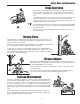
Operating the Tractor USING A MULCHING MOWER (40” MOWER ONLY) B Benefits of Proper Mulching Mulching consists of a mower deck which cuts and recuts clippings into tiny particles and then blows them down into the lawn. These tiny particles decompose rapidly into by-products that your lawn can use. Under proper conditions your mulching mower virtually eliminates noticeable clippings on the lawn surface.
Operating the Tractor ADJUSTING MOWER CUTTING HEIGHT The cutting height adjustment knob (A, Figure 5) controls the mower cutting height. Turn the knob clockwise to raise the deck and counterclockwise to lower it. A Figure 5. Raising & Lowering Mower A.
Operating the Tractor WARNING Engage parking brake, disengage PTO, stop engine and remove key before pivoting the mower. MOWER DECK SERVICE ACCESS Pivoting the Mower Deck Up A 1. Engage the parking brake, disengage the PTO, stop the engine, and remove the key. B Figure 6. Mower Deck Access A. Idler Lever B. Pins & Clips (Both Sides) 2. Place the mower lift lever between the raised and lowered notches. Place the height of cut control in the lowest position. 3.
Operating the Tractor STORAGE WARNING • Battery life will be increased if it is removed, put in a cool, dry place and fully charged about once a month. If the battery is left in the unit, disconnect the negative cable. Never store the unit (with fuel) in an enclosed, poorly ventilated structure. Fuel vapors can travel to an ignition source (such as a furnace, water heater, etc.) and cause an explosion. Before starting the unit after it has been stored: • Check all fluid levels.
Regular Maintenance MAINTENANCE SCHEDULE The following schedule should be followed for normal care of your tractor and mower. Use the hour meter to determine your operating time.
Regular Maintenance CHECK TIRE PRESSURES Service Interval: Every 25 Hours Tire Pressure should be checked periodically, and maintained at the levels shown in the chart. Note that these pressures may differ slightly from the “Max Inflation” stamped on the side-wall of the tires. The pressures shown provide proper traction, improve cut quality, and extend tire life. TRANSMISSION IDENTIFICATION Size Several service procedures within this book are identified by, and vary by, transmission type.
Regular Maintenance BATTERY MAINTENANCE B WARNING When removing or installing battery cables, disconnect the negative cable FIRST and reconnect it LAST. If not done in this order, the positive terminal can be shorted to the frame by a tool. C Cleaning the Battery and Cables Service Interval: Every 100 Hours 1. Disconnect the cables from the battery, negative cable first (A, Figure 11). A 2. Remove the battery hold-down (C) and battery. Figure 11. Battery A. Negative Cable B. Positive Cable & Cover C.
Regular Maintenance LUBRICATION Service Interval: Every 25 Hours Lubricate the unit at the locations shown in Figures 1214 as well as the lubrication points listed. Generally, all moving metal parts should be oiled where contact is made with other parts. Keep oil and grease off belts and pulleys. Wipe surfaces clean before and after lubrication. Grease: • steering linkage • foot pedal • mower linkage • transmission idler assembly pivot • rear axle shafts (remove wheel hubs) Use grease fittings when present.
Regular Maintenance LUBRICATE AXLE SHAFTS A Service Interval: Yearly B We recommend removing the wheel hubs and lubricating the axle shafts yearly. This prevents the wheel hubs from seizing onto the axle shaft and makes future service easier. D C 1. Turn off the ignition, turn off the PTO, engage the parking brake, and block the front tires. 2.
Regular Maintenance WARNING For your personal safety, do not handle the sharp mower blades with bare hands. Careless or improper handling of blades may result in serious injury. WARNING For your personal safety, blade mounting capscrews must each be installed with a hex/spline washer and spring washer, then securely tightened. Torque blade mounting capscrew to 45 - 55 ft. lbs. (61 - 75 N.m.) Figure 16.
Regular Maintenance CHECK MOWER BLADE TIMING 40” MOWERS Service Interval: Yearly B 1. Turn the PTO to the off position, engage the parking brake, turn the engine off, and remove the key. Remove the mower deck (see “Mower deck removal”). C D E G F 2. Turn the mower deck over and check the position of the blades. The blades must be positioned perpendicular to each other as shown in Figure 20. If not, proceed to step 3. A 3.
Troubleshooting, Adjustment, & Service TROUBLESHOOTING WARNING While normal care and regular maintenance will extend the life of your equipment, prolonged or constant use may eventually require that service be performed to allow it to continue operating properly. To avoid serious injury, perform maintenance on the tractor or mower only when the engine is stopped and the parking brake engaged.
Troubleshooting, Adjustment, & Service Troubleshooting the Tractor — Continued SYMPTOM PROBLEM SOLUTION Tractor drive belt slips. 1. 2. 3. 4. 1. See authorized service dealer. 2. Clean as required. 3. Replace belt. 4. Remove idler bracket, clean and lubricate. Brake will not hold. Tractor steers hard or handles poorly. Drive belt does not stop when clutch/brake pedal depressed. Clutch is out of adjustment. Pulleys or belt greasy or oily. Belt stretched or worn.
Troubleshooting, Adjustment, & Service SEAT ADJUSTMENT Seat Slide Adjustment The seat can also be adjusted forward and back. Move the lever (A, Figure 21), position the seat as desired, and release the lever to lock the seat into position. TRANSMISSION PURGING A Purge the transmission if the unit is excessively noisy or lacks drive in forward or reverse. 1. Elevate the front end of the tractor using a chain hoist or floor jack. Support the front of the unit using jackstands.
Troubleshooting, Adjustment, & Service STEERING WHEEL ADJUSTMENT B C 1. Use a suitable punch to remove the roll pin at the base of the steering wheel (B, Figure 22). 2. Pull down on the rubber boot to expose the two holes in the steering shaft (A). Thicker Spoke Faces Seat 3. Align the hole in the steering wheel with the appropriate steering shaft hole and install the roll pin. A NOTE: Steering wheel is factory installed with the roll pin in the top hole.
Troubleshooting, Adjustment, & Service PTO CLUTCH ADJUSTMENT A B WARNING To avoid serious injury, perform adjustments only with engine stopped, key removed and tractor on level ground. Check the PTO clutch adjustment after the initial 25 hour break-in period and then after every 250 hours of operation. Also perform the following procedure if the clutch is slipping or will not engage, or if a new clutch has been installed. B B 1.
Troubleshooting, Adjustment, & Service MOWER ADJUSTMENTS Leveling The Mower If the cut is uneven, the mower may need leveling. Unequal or improper tire pressure may also cause an uneven cut. Make sure tire pressure is correct as specified in Checking Tire Pressure. A 1. With the mower installed, place the tractor on a smooth, level surface such as a concrete floor. Turn the rear wheels straight forward. B 2. Check for bent blades and replace if necessary. SIDE-TO-SIDE LEVELING - EARLY MODELS 3.
Troubleshooting, Adjustment, & Service FRONT-TO-BACK LEVELING - 40” MODELS 6. Arrange the blades so they face front-to-back. D 7. Measure the distance from the ground to front tip and rear tip of the left and right-hand blades. Front tips should be 1/8”-1/4” (3mm-6mm) higher. If not, proceed with steps 8 - 10. B C A 8. See Figure 28. To raise front of mower deck, loosen front nut (A) and turn rear nut (B) against bracket (C). 9.
Troubleshooting, Adjustment, & Service MOWER BELT REPLACEMENT E D 40” Mower PTO Belt Replacement 1. With the mower deck installed, park the tractor on a smooth, level surface such as a concrete floor. Disengage the PTO, engage the parking brake, shut the engine off, and remove the key. 2. Remove the right belt cover. 3. Move the spring loaded lever to relieve tension on the PTO belt. Remove the PTO belt from the idler (D, Figure 30) and engine pulley (B). 4.
Troubleshooting, Adjustment, & Service D A B C A Figure 33. Release Cogged Belt Tension A. 3/8” Ratchet and Extension Figure 32. Mulching Deck (Belt Covers Removed) A. Idler Assembly Capscrew B. Spring-Loaded Idler Assembly C. Belt D. Square Hole 40” Mower Arbor Drive Belt Replacement 1. With the mower deck installed, park the tractor on a smooth, level surface such as a concrete floor. Disengage the PTO, engage the parking brake, shut the engine off, and remove the key. Figure 34.
Troubleshooting, Adjustment, & Service C B A A D A B Figure 36. Mower Deck Drive Belt Routing All Models A. Arbor Drive Pulley (V-sided) B. Idler Pulley (Flat-sided) Figure 35. Mower Deck - 44" & 50” Mowers A. Capscrew B. Left-hand Arbor Cover C. Right-hand Arbor Cover D. Spring 44” Mower Arbor Drive Belt Replacement NOTE: Be sure to use only genuine Simplicity replacement parts. 1. Park the tractor on a smooth, level surface such as a concrete floor.
Specifications, Parts, & Accessories NOTE: Specifications are correct at time of printing and are subject to change without notice. * Actual sustained equipment horsepower will likely be lower due to operating limitations and environmental factors. ENGINE: CHASSIS: 15 HP* Fuel Tank Cap. Rear Wheels Make Model Horsepower Displacement Electrical System Oil Capacity Briggs & Stratton OHV 31F777 15 @ 3600 rpm 30.6 Cu. in (502 cc) 12 Volt, 16 amp. Alternator, Battery: 230 CCA 1.
MANUFACTURING, INC. 500 N Spring Street / PO Box 997 Port Washington, WI 53074-0997 www.simplicitymfg.com Briggs & Stratton Yard Power Products Group Copyright © 2007 Briggs & Stratton Corporation Milwaukee, WI USA.