Print Instructions for Print Vendors (Paper Manuals) OPERATOR’S MANUAL TOTAL PAGE COUNT: Less than 45 Paper Size: • 11 x 17 • Body - 50 lbs brilliant white offset or equivalent. • Cover - on 80 lbs coated cover stock (NOTE: If total order quantity is less than 100 pieces, use uncoated cover stock) Press: • Body - 1-color, 2-sided • Cover - 1-color, 2-sided Bindery: • Staple (2X), Face Trim TOTAL PAGE COUNT: 45 or greater Paper Size: • 8-1/2 x 11 • Body - 50 lbs brilliant white offset or equivalent.
THIS PAGE INTENTIONALLY BLANK
TM OPERATOR’S MANUAL The Stallion Zero-Turn Riding Mower Model: ZT2354 mowers are built by Ferris Industries, a Simplicity company.
Ferris Industries 5375 North Main Street Munnsville, NY 13409 800-933-6175 www.ferrisindustries.com © Copyright 2000 Ferris Industries All Rights Reserved. Printed in USA.
Table of Contents Troubleshooting, Adjustments & Service .......23 Identification Numbers .......................................2 Safety Rules & Information ................................3 Features & Controls ............................................6 Troubleshooting the Tractor ..................................23 Troubleshooting the Mower ..................................24 Seat Adjustment....................................................25 Ground Speed Control Lever Adjustment .............
Identification Numbers IDENTIFICATION TAG LOCATIONS When contacting your Authorized Dealer for replacement parts, service, or information YOU MUST HAVE THESE NUMBERS. XXXXXXX Tractor identification tag XXXXXXX IDENTIFICATION NUMBERS PRODUCT Record your model name/number, unit and mower deck manufacturer numbers and engine serial number in the space provided for easy reference.
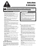
Safety Rules & Information Read these safety rules and follow them closely. Failure to obey these rules could result in loss of control of unit, severe personal injury or death to you, or bystanders, or damage to property or equipment. This mowing deck is capable of amputating hands and feet and throwing objects. The triangle in text signifies important cautions or warnings which must be followed.
Safety Rules & Information CHILDREN • Never run a unit in an enclosed area. Tragic accidents can occur if the operator is not alert to the presence of children. Children are often attracted to the unit and the mowing activity. Never assume that children will remain where you last saw them. • Keep nuts and bolts, especially blade attachment bolts, tight and keep equipment in good condition. • Never tamper with safety devices. Check their proper operation regularly.
Safety Rules & Information SAFETY DECALS All DANGER, WARNING, CAUTION and instructional messages on your rider and mower should be carefully read and obeyed. Personal bodily injury can result when these instructions are not followed. The information is for your safety and it is important! The safety decals below are on your rider and mower.
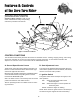
Features & Controls of the Zero Turn Rider Please take a moment and familiarize yourself with the name, location, and function of these controls so that you will better understand the safety and operating instructions provided in this manual. A A H B E L F J D C K G I Figure 1. Control Locations CONTROL FUNCTIONS The information below briefly describes the function of individual controls.
Features & Controls SAFETY INTERLOCK SYSTEM D. Parking Brake Handle The parking brake is applied by pulling UP on the parking brake handle until it locks over-center. To release the parking brake, push the handle DOWN. This unit is equipped with safety interlock switches and other safety devices. These safety systems are present for your safety, do not attempt to bypass safety switches, and never tamper with safety devices. Check their operation regularly. E.
Operating the Zero Turn Rider GENERAL OPERATING SAFETY WARNING Before first time operation: • Be sure to read all information in the Safety and Operation sections before attempting to operate this tractor and mower. Never allow passengers to ride on the unit. Before leaving the operator’s position for any reason, engage the parking brake, disengage the PTO, stop the engine and remove the key. • Become familiar with all of the controls and how to stop the unit.
Operating the Zero Turn Rider WARNING MOWING 1. Engage the parking brake. Make sure the PTO switch is disengaged, the motion control handles are locked in the NEUTRAL position and the operator is on the seat. 2. Start the engine (see STARTING THE ENGINE). 3. Set the mower cutting height. 4. Set the throttle to FULL. 5. Engage the PTO by pulling up on the PTO switch (E, Figure 1). 6. Begin mowing. See Section C for tips on mowing patterns, lawn care, and trouble shooting information. 7.
Operating the Zero Turn Rider ZERO TURN DRIVING PRACTICE The lever controls of the Zero Turn rider are responsive, and learning to gain a smooth and efficient control of the rider’s forward, reverse, and turning movements will take some practice. Spending some time going through the maneuvers shown and becoming familiar with how the unit accelerates, travels, and steers — before you begin mowing — is absolutely essential to getting the most out of the Zero Turn rider.
Operating the Zero Turn Rider Practice Turning Around a Corner Practice Turning In Place While traveling forward allow one handle to gradually return back toward neutral. Repeat several times. To turn in place, “Zero Turn,” gradually move one ground speed control lever forward from neutral and one lever back from neutral simultaneously. Repeat several times. NOTE: To prevent pivoting directly on the tire tread, it is best to keep both wheels going at least slightly forward.
Operating the Zero Turn Rider MOWER DECK REMOVAL & INSTALLATION Removing the Mower Deck NOTE: Perform mower removal on a hard, level surface such as a concrete floor. A WARNING Engage parking brake, disengage PTO, stop engine and remove key before attempting to install or remove the mower. 1. Push the deck lift pedal forward until it locks in the “TRANSPORT” position and remove the height adjustment pin. 2. Place two, 2” x 4” blocks (B, Figure 10) under the outside edges of the mower. 3.
Operating the Zero Turn Rider Installing the Mower Deck NOTE: Perform mower installation on a hard, level surface such as a concrete floor. D WARNING C Engage parking brake, disengage PTO, stop engine and remove key before attempting to install or remove the mower. 1. Slide the mower under the tractor. 2. Install the bar mount pins (C, Figure 12) to secure the pusher bars (A, Figure 12) to the mower. 3. Place two, 2” x 4” blocks (B, Figure 10) under the outside edges of the mower. 4.
Operating the Zero Turn Rider STORAGE WARNING Temporary Storage (30 Days Or Less) Never store the unit, with gasoline in engine or fuel tank, in a heated shelter or in enclosed, poorly ventilated enclosures. Gasoline fumes may reach an open flame, spark or pilot light (such as a furnace, water heater, clothes dryer, etc.) and cause an explosion.
Notes 15
Regular Maintenance MAINTENANCE SCHEDULE & PROCEDURES The following schedule should be followed for normal care of your rider and mower. You will need to keep a record of your operating time. Determining operating time is easily accomplished by observing the elapsed time recorded by the hour meter.
Regular Maintenance CHECKING / ADDING FUEL WARNING To add fuel: 1. Remove the fuel cap (see A, Figure 2). 2. Fill the tank. Do not overfill. Leave approximately 1” of room in the tank for fuel expansion. Refer to your engine manual for specific fuel recommendations. 3. Install and hand tighten the fuel cap. Gasoline is highly flammable and must be handled with care. Never fill the tank when the engine is still hot from recent operation. Do not allow open flame, smoking or matches in the area.
Regular Maintenance LUBRICATION Lubricate the unit at the locations shown in Figures 16 through 22 as well as the following lubrication points. Grease: • • • • • • • • front caster wheel axles motion control pivots suspension a-arms rear deck mounts deck lift pivots deck lift foot pedal front pivot frame mower arbors Use grease fittings when present. Disassemble parts to apply grease to moving parts when grease fittings are not installed. Not all greases are compatible.
Regular Maintenance Figure 19. Suspension Lubrication Top & Bottom, Left & Right Figure 22. Front Pivot Frame Lubrication (Front location shown, rear grease fitting located through clearance hole in brake cover panel.) Figure 20. Rear Control Pivot Lubrication Figure 21.
Regular Maintenance WARNING BATTERY MAINTENANCE Checking the Battery Fluid Be careful when handling the battery. Avoid spilling electrolyte. Keep flames and sparks away from the battery. 1. Raise the seat plate to access battery. 2. Remove the rubber strap and battery box cover. When removing or installing battery cables, disconnect the negative cable FIRST and reconnect it LAST. If not done in this order, the positive terminal can be shorted to the frame by a tool. 3.
Regular Maintenance SERVICING THE MOWER BLADES 1. Remove mower from the rider. See Mower Installation & Removal. 2. Blades should be sharp and free of nicks and dents. If not, sharpen blades as described in following steps. 3. To remove blade for sharpening, use a wood block to hold blade while removing the blade mounting capscrew (Figure 24). 4. Use a file to sharpen blade to fine edge. Remove all nicks and dents in blade edge. If blade is severely damaged, it should be replaced. 5.
Notes 22
Troubleshooting Adjustments & Service TROUBLESHOOTING WARNING While normal care and regular maintenance will extend the life of your equipment, prolonged or constant use may eventually require that service be performed to allow it to continue operating properly. To avoid serious injury, perform maintenance on the tractor or mower only when the engine is stopped and the parking brake engaged. The troubleshooting guide below lists the most common problems, their causes and remedies.
Troubleshooting, Adjustment & Service Rider Troubleshooting Continued. PROBLEM CAUSE REMEDY Engine runs, but rider will not drive. 1. Hydraulic release valve(s) in “open” position. 2. Belt is broken. 3. Drive belt slips. 4. Brake is not fully released. 1. Clutch is out of adjustment. 2. Pulleys or belt greasy or oily. 3. Belt stretched or worn. 1. Brake is incorrectly adjusted. 2. Brake caliper pads worn. 1. Steering linkage is loose. 2. Improper tire inflation. 1. Turn valve(s) clockwise to close.
Troubleshooting, Adjustment & Service SEAT ADJUSTMENT See Figure 27. The seat can be adjusted forward and back. Move the lever forward, position the seat as desired, and release the lever to lock the seat into position. Seat Adjustment Lever GROUND SPEED CONTROL LEVER ADJUSTMENT The control levers can be adjusted in two ways. The alignment of the control levers can be adjusted along with the placement of the levers (how close the ends are to one another) can be adjusted. Figure 27.
Troubleshooting, Adjustment & Service PARKING BRAKE ADJUSTMENT FRONT 1. Disengage the PTO, stop the engine, block the front wheels, remove the ignition key, and engage the parking brake. A 2. Remove both control covers. 3. Locate the upper brake spring (A, Figure 30). 4. With the parking brake engaged, measure the compressed spring length. The spring should be 2” to 21/8” (5.0 - 5.4cm) when compressed. 5. If the spring is not within this range, jack up the rear of the machine and secure with jackstands.
Troubleshooting, Adjustment & Service A B B B C B A Figure 34. Adjust PTO Clutch A. Window B. Adjustment Nut C. .010”-.015” (2.5-4mm) Feeler Gauge Figure 33. PTO Clutch Adjustment A. Adjustment Window (Qty. 3, one shown) B. Adjustment Nut WARNING PTO CLUTCH ADJUSTMENT Check the PTO clutch adjustment after the initial 50 hour break-in period and then after every 250 hours of operation.
Troubleshooting, Adjustment & Service NEUTRAL ADJUSTMENT If the tractor “creeps” while the ground speed control levers are locked in NEUTRAL, than it may be necessary to adjust the control linkage. A B NOTE: Perform this adjustment on a hard, level surface such as a concrete floor. 1. Disengage the PTO, engage the parking brake and turn off the engine. 2. Loosen the jam nut (B, Figure 35) and turn the adjustment linkage (A, Figure 35) to adjust.
Troubleshooting, Adjustment & Service MOWER ADJUSTMENTS A WARNING B Before checking mower, shut off PTO and engine. Allow all moving parts to stop. Remove ignition key, then disconnect the spark plug wire and fasten it away from the spark plug. Gauge Wheels The mower gauge wheels can be placed in two positions depending on the height of cut. When using higher cutting heights, set the wheels in the lower position. When using lower cutting heights, set the wheels in the upper position.
Troubleshooting, Adjustment & Service HYDRAULIC PUMP DRIVE BELT REPLACEMENT FRONT E 1. Park the tractor on a smooth, level surface such as a concrete floor. Disengage the PTO, engage the parking brake, turn off the engine, and remove the ignition key. H F F D E G 2. Remove the PTO drive belt (see section below for instructions). A 3. Remove the nuts fastening the spring anchor bolts (H, Figure 40) to the anchor arm. 4. Remove the old belt and replace it with the new one.
Troubleshooting, Adjustment & Service Arbor Drive Belt Replacement A NOTE: Be sure to use only genuine Simplicity replacement parts. 1. Park the tractor on a smooth, level surface such as a concrete floor. Disengage the PTO, turn off the engine and lock the parking brake. Remove the key. C A 2. Remove the PTO belt. 3. Remove the capscrews (A, Figure 43) securing the right-hand arbor cover (B, Figure 43). Remove the capscrews (A, Figure 43) securing the left-hand arbor cover (D, Figure 43).
Troubleshooting, Adjustment & Service BATTERY SERVICE 6. Charge the battery until fully charged (until the specific gravity of the electrolyte is 1.250 or higher and the electrolyte temperature is at least 60° F). The best method of making certain a battery is fully charged, but not over charged, is to measure the specific gravity of a cell once per hour. The battery is fully charged when the cells are gassing freely at low charging rate and less than 0.
Troubleshooting, Adjustment & Service THIS HOOK-UP FOR NEGATIVE GROUND VEHICLES To Starter Switch To Starter Switch Jumper Cable Starting Vehicle Battery Discharged Vehicle Battery Jumper Cable To Ground Engine Block MAKE CERTAIN VEHICLES DO NOT TOUCH Figure 45.
Notes 34
Lawn Care & Mowing Information GENERAL INFORMATION • • • • • • • Proper mowing is an important part of maintaining your lawn in the best possible condition. A healthy and well maintained lawn is better able to resist drought, weeds, and other stresses. But too much maintenance is as detrimental to your lawn as neglect. Proper care for your lawn involves more than just “cutting the grass.
Lawn Care & Mowing Information HOW HIGH TO MOW THE GRASS Cut less than 1/3 Often cutting height is a matter of personal preference. Typically, you should mow the grass when it is is between three and five inches high. The proper cutting height range for a specific lawn will depend upon several factors, including the type of grass, the amount of rainfall, the prevailing temperature, and the lawn’s overall condition.
Lawn Care & Mowing Information WHEN AND HOW OFTEN TO MOW The time of day and condition of the grass greatly affect the results you’ll get when mowing. For the best results, follow these guidelines: l Mow when the grass is between three and five inches high. l Mow with sharp blades. Short clippings of grass one inch or shorter decompose more quickly than longer blades. Sharp mower blades cut grass cleanly and efficiently, preventing frayed edges which harm the grass.
Lawn Care & Mowing Information MOWING METHODS Proper Broadcast Mowing Broadcasting, or side-discharging, disperses fine clippings evenly over the entire lawn. Many golf courses use this method. Your mower has a deep dish deck to allow freer circulation of clippings so they are broadcast evenly over the lawn. ENGINE SPEED & GROUND SPEED FOR BROADCASTING Always operate the engine at full throttle when mowing.
Lawn Care & Mowing Information TIPS On Dealing With Clippings Clippings are beneficial to your lawn. A common misconception about clippings is that they automatically lead to thatch—this is untrue.
Lawn Care & Mowing Information SOLUTIONS FOR COMMON MOWING PROBLEMS ;;;;;;;;; ; ;; ;;;;;;;;; ; ;; ;;;;;;;;; ; ;; Streaking Streaking Streaking is when thin strips of uncut grass are left behind the mower. Streaking is usually caused by operator error or poor blade maintenance.
Lawn Care & Mowing Information ;;;;; ;;;;; ;;;;; ;;;;; ;;;;; ;;;;; Uneven Cutting Uneven Cutting Uneven cutting is waviness or smooth troughs in the lawn surface. Uneven cutting is usually caused by mower deck damage or misadjustment.
Common International Symbols PTO Clutch Choke Fast (Throttle) Parking Brake Slow (Throttle) Brake Throttle Mower Cutting Height Adjustment Fuel Headlights Technical Manuals Additional Technical Literature Available Operators Manuals Additional copies of this manual are available, (and as part of our product support commitment, we maintain a stock of printed operators manuals going back many years!) Parts Manuals Fully illustrated parts manuals are also available — these manuals show all of the produc
Notes LC-9