Safety Instructions & Operator's Manual for REAR ENGINE RIDING MOWER SERIES 23 Models 2811523BV (7800102) 2812523BVE (7800104) 3011523BV (7800103) 3012523BVE (7800105) 3317523BVE (7800254) NOTE: Specifications are correct at time of printing and are subject to change without notice. * Actual sustained engine power will likely be lower due to operating limitations and environmental factors. Please refer to ‘Engine Power Rating Information’ for further details. Manual No. 7101572 (I.R.
Thank You for purchasing this quality-built Snapper product. We’re pleased that you placed your confidence in the Snapper brand. When operated and maintained according to the instructions in this manual, your Snapper product will provide many years of dependable service. This manual contains safety information to make you aware of the hazards and risks associated with the machine and how to avoid them.
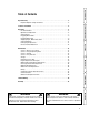
Operator Safety Table of Contents Operator Safety . . . . . . . . . . . . . . . . . . . . . . . . . . . . . . . . . . . . . . . . . . . . . . . .2 Important Operator Safety Instructions . . . . . . . . . . . . . . . . . . . . . . . . . . . . . . . . . .2 Features and Controls Features and Controls . . . . . . . . . . . . . . . . . . . . . . . . . . . . . . . . . . . . . . . . . . .5 Operation Operation . . . . . . . . . . . . . . . . . . . . . . . . . . . . . . . . . . . . . . . . . . . . . . . . . . .
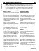
! ! Important Operator Safety Instructions Operator Safety WARNING: This powerful cutting machine is capable of amputating hands and feet and can throw objects that can cause injury and damage! Failure to comply with the following SAFETY instructions could result in serious injury or death to the operator or other persons. The owner of the machine must understand these instructions and must allow only persons who understand these instructions to operate machine.
! Important Operator Safety Instructions (Continued) Protection against Tipovers Safe Handling of Gasoline To avoid personal injury or property damage, use extreme care in handling gasoline. Gasoline is extremely flammable and the vapors are explosive. 1. Extinguish all cigarettes, cigars, pipes and other sources of ignition. 2. Use only an approved fuel container. 3. DO NOT remove fuel cap or add fuel with the engine running. Allow the engine to cool before refueling. 4.
! Important Operator Safety Instructions (Continued) Operator Safety Towing 1. Tow only with a machine that has a hitch designed for towing. DO NOT attach towed equipment except at the hitch point. 2. Follow the manufacturer’s recommendation for weight limits for towed equipment and towing on slopes. 3. DO NOT allow children or others on towed equipment. 4. On slopes, the weight of the towed equipment may cause loss of traction and loss of control. 5. Travel slowly and allow extra distance to stop.
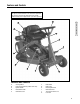
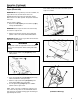
Features and Controls IMPORTANT The figures and illustrations in this manual are provided for reference only and may differ from your specific model. Contact your Snapper dealer if you have questions. A Features and Controls K J B C D I H G F E Features and Controls A. B. C. D. E. Steering Wheel Engine Speed Control (hidden from view) Ignition Switch Clutch/Brake Pedal Park Brake Latch F. G. H. I. J. K.
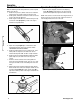
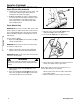
Operation Pre-Start Check List Operator Seat Adjustment Make the following checks and perform the service required before each start-up: 1. Check the tire pressure; add or release air as needed to bring pressure to 12 PSI in front and 12 PSI in rear. 2. Check guards, deflectors and covers to make sure all are in place and securely tightened. 3. Check engine oil and add oil as needed to bring level up to the FULL mark (A, Figure 1). Refer to the engine manual for oil specifications. 1.
Operation (Continued) Starting and Operation 7. After the engine starts, move the engine speed control to the “FAST” position and allow a brief warm-up until engine runs smooth. Engine (Electric Start) IMPORTANT: When the ignition key is turned to “START”, the engine will turn over, but will not start unless the Clutch/Brake pedal is pressed all the way down, and the Blade Lever is in the “OFF” position. The operator should be in the seat. A Start the engine as follows: 1.
Operation (Continued) Starting and Operation (Continued) A Engine (Electric Start) (Continued) 8. Should the battery be too weak to start the engine, refer to the Section entitled “Engine (Manual Start)” to manually start the electric start engines. 9. On Model 3314522BVE, the engine is equipped with a fuel shut-off solenoid. If the battery is dead, the engine can be started with the recoil back-up starter if the engine speed control is in the choke position (HOT engine or COLD engine).
Operation (Continued) WARNING ! ! Once blade is disengaged, it should come to a complete stop in 3 seconds or less. If the blade continues to rotate after 3 seconds, the blade brake must be adjusted. Refer to Section “BLADE BRAKE ADJUSTMENT” for adjustment procedures or return machine to an authorized SNAPPER dealer for adjustment. DO NOT CONTINUE to operate machine until blade brake is adjusted and functioning properly. ! ! WARNING DO NOT operate blades in reverse. STOP BLADES.
Operation (Continued) ! ! WARNING DO NOT leave the machine with the engine running. STOP Blade. STOP engine. Shift to neutral and engage park brake. Remove key. Mower Blade 1. Stop the mower blade by releasing the blade pedals (A, Figure 15) or moving the blade lever (B) rearward to the “OFF” position. B Stopping - Engine, Wheel Drive, Blade Engine 1. Stop the engine by turning the key (A, Figure 13) to the “OFF” position.
Operation (Continued) Stopping - Engine, Wheel Drive, Blade (Continued) Cutting Height Adjustment 1. Adjust the cutting height by raising or lowering the deck lift lever (A, Figure 18) into the desired height of cut notch (B). Park Brake 1. To set the park brake, press the clutch/brake pedal (A, Figure 16) all the way down, slide the park brake latch (B) all the way in to the engaged position, and release the clutch/brake pedal. A detent in the park brake latch will keep the park brake engaged.
Operation (Continued) Reverse Lockout Mechanism Data indicates that tragic back-over accidents occur each year. These accidents usually involve unsupervised children. Many times these children have been given rides on the machine and have been trained to view this potentially dangerous piece of machinery as fun rather than being taught how to avoid danger. Operation This riding mower has a Reverse Lockout Mechanism. This mechanism prevents the mower from being shifted into reverse with the blade running.
Maintenance ! WARNING ! DO NOT attempt any adjustments, maintenance, service or repairs with the engine running. STOP engine. STOP blade. Engage parking brake. Remove key. Remove spark plug wire from spark plug and secure away from plug. Engine and components are HOT. Avoid serious burns, allow all parts to cool before working on machine. Fuel Filler Cap and vent must be closed securely to prevent fuel spillage. 5.
Maintenance (Continued) ! ! WARNING DO NOT attempt any adjustments, maintenance, service or repairs with the engine running. STOP engine. STOP blade. Engage parking brake. Remove key. Remove spark plug wire from spark plug and secure away from plug. Engine and components are HOT. Avoid serious burns, allow all parts to cool before working on machine. Fuel Filler Cap and vent must be closed securely to prevent fuel spillage.
Maintenance (Continued) Service - After the First 5 Hours (Continued) Service - Every 25 Operating Hours Perform all service required after the first 5 hours of operation. Refer to the section entitled “SERVICE – AFTER 5 HOURS”. Safety Interlock System Checks Perform the following interlock system checks periodically during the operating season. Contact your authorized Snapper dealer if you have questions.
Maintenance (Continued) ! WARNING ! DO NOT attempt any adjustments, maintenance, service or repairs with the engine running. STOP engine. STOP blade. Engage parking brake. Remove key. Remove spark plug wire from spark plug and secure away from plug. Engine and components are HOT. Avoid serious burns, allow all parts to cool before working on machine. Fuel Filler Cap and vent must be closed securely to prevent fuel spillage.
Maintenance (Continued) ! WARNING ! DO NOT attempt any adjustments, maintenance, service or repairs with the engine running. STOP engine. STOP blade. Engage parking brake. Remove key. Remove spark plug wire from spark plug and secure away from plug. Engine and components are HOT. Avoid serious burns, allow all parts to cool before working on machine. Fuel Filler Cap and vent must be closed securely to prevent fuel spillage. Service - Every 25 Operating Hours (Continued) 2.
Maintenance (Continued) ! ! WARNING DO NOT attempt any adjustments, maintenance, service or repairs with the engine running. STOP engine. STOP blade. Engage parking brake. Remove key. Remove spark plug wire from spark plug and secure away from plug. Engine and components are HOT. Avoid serious burns, allow all parts to cool before working on machine. Fuel Filler Cap and vent must be closed securely to prevent fuel spillage.
Maintenance (Continued) ! WARNING ! DO NOT attempt any adjustments, maintenance, service or repairs with the engine running. STOP engine. STOP blade. Engage parking brake. Remove key. Remove spark plug wire from spark plug and secure away from plug. Engine and components are HOT. Avoid serious burns, allow all parts to cool before working on machine. Fuel Filler Cap and vent must be closed securely to prevent fuel spillage.
Maintenance (Continued) ! ! WARNING DO NOT attempt any adjustments, maintenance, service or repairs with the engine running. STOP engine. STOP blade. Engage parking brake. Remove key. Remove spark plug wire from spark plug and secure away from plug. Engine and components are HOT. Avoid serious burns, allow all parts to cool before working on machine. Fuel Filler Cap and vent must be closed securely to prevent fuel spillage.
Maintenance (Continued) ! WARNING ! DO NOT attempt any adjustments, maintenance, service or repairs with the engine running. STOP engine. STOP blade. Engage parking brake. Remove key. Remove spark plug wire from spark plug and secure away from plug. Engine and components are HOT. Avoid serious burns, allow all parts to cool before working on machine. Fuel Filler Cap and vent must be closed securely to prevent fuel spillage. B A Mower Drive Belt Adjustment (For 28” & 30” Decks Only) 1.
Maintenance (Continued) ! ! WARNING E DO NOT attempt any adjustments, maintenance, service or repairs with the engine running. STOP engine. STOP blade. Engage parking brake. Remove key. Remove spark plug wire from spark plug and secure away from plug. Engine and components are HOT. Avoid serious burns, allow all parts to cool before working on machine. Fuel Filler Cap and vent must be closed securely to prevent fuel spillage.
Maintenance (Continued) ! ! WARNING DO NOT attempt any adjustments, maintenance, service or repairs with the engine running. STOP engine. STOP blade. Engage parking brake. Remove key. Remove spark plug wire from spark plug and secure away from plug. Engine and components are HOT. Avoid serious burns, allow all parts to cool before working on machine. Fuel Filler Cap and vent must be closed securely to prevent fuel spillage. 4.
Maintenance (Continued) ! WARNING ! DO NOT attempt any adjustments, maintenance, service or repairs with the engine running. STOP engine. STOP blade. Engage parking brake. Remove key. Remove spark plug wire from spark plug and secure away from plug. Engine and components are HOT. Avoid serious burns, allow all parts to cool before working on machine. Fuel Filler Cap and vent must be closed securely to prevent fuel spillage.
Maintenance (Continued) ! ! WARNING DO NOT attempt any adjustments, maintenance, service or repairs with the engine running. Stop engine. Stop blade. Engage parking brake. Remove key. Remove spark plug wire from spark plug and secure away from plug. Engine and components are HOT. Avoid serious burns, allow all parts to cool before working on machine. Fuel Filler Cap and Vent must be closed securely to prevent fuel spillage.
Maintenance (Continued) ! WARNING ! The electrolyte (acid) produces a highly explosive gas. Keep all sparks, flame and fire away from area when charging battery or when handling electrolyte or battery. Electrolyte (acid) is a highly corrosive liquid. Wear eye protection. Wash affected areas immediately after having eye or skin contact with electrolyte (acid). Battery acid is corrosive. Rinse empty acid containers with water and mutilate before discarding.
Maintenance (Continued) Battery Testing (Continued) State of Charge 100% Charged w/ Sulfate Stop 100% Charged 75% Charged 50% Charged 25% Charged 0% Charged Battery Condition Chart Syringe Hydrometer Digital Voltmeter 1.280 12.80v 1.265 12.60v 1.210 12.40v 1.160 12.10v 1.120 11.90v Less than 1.100 Less than 11.
Maintenance (Continued) Service Schedule ITEM SERVICE PERFORMED REF.
Maintenance (Continued) Maintenance/Replacement Parts Engine Speed Control (Briggs Engine) Engine Speed Control (Kohler Engine) Engine Speed Control (Honda Engine) Clutch/Brake Cable Clutch/Brake Cable (33” Deck Models Only) Brake Cable 28” Cutter Blade (Standard - Not Air Lift Compatible) 28” Cutter Blade (Standard - Air Lift Compatible) 28” Cutter Blade (Mulching) 28” Cutter Blade (Ninja - Quad Edge) 30” Cutter Blade (Standard - Not Air Lift Compatible) 30” Cutter Blade (Standard - Air Lift Compatible) 30
Troubleshooting PROBLEM PROBABLE CAUSE Troubleshooting Engine Will Not 1. Fuel tank empty. Start Using 2. Engine needs choking. Recoil Starter 3. Spark plug wire disconnected. 4. Faulty parking brake, blade or ignition switch. 5. Park brake not engaged. 6. Ignition is in the OFF position. Engine Will Not 1. Fuel tank empty. Start Using 2. Engine needs choking. Electric Starter 3. Spark plug wire disconnected. 4. Faulty parking brake, blade or ignition switch. 5. Park brake not engaged. 6. Blown Fuse. 7.
Troubleshooting (Continued) PROBLEM PROBABLE CAUSE CORRECTIVE ACTION Rider Will Not Move Or Loss of Traction 1. Drive disc worn or damaged. 2. Rubber drive disc is not tracking properly on drive disc. 3. Tapered axle bolt and nut missing. 4. Axle bearing seized. 5. Insufficient lubrication in chain case or transmission/differential. 1. Blade engagement lever in the “OFF” position. 2. Mower belt slipping. 3. Cutting blade is dull, worn or damaged. 1. Uneven tire pressure. 1. Replace drive disc. 2.
2 YEAR LIMITED WARRANTY For two (2) years from purchase date for the original purchaser’s residential, non-commercial use, SNAPPER, through any authorized SNAPPER dealer will replace, free of charge (except for taxes where applicable), any part or parts found upon examination by the factory at McDonough, Georgia, to be defective in material or workmanship or both.
Slope Guide 33
Notes 34 www.snapper.
Notes 35
Notes 36 www.snapper.
Notes 37
REAR ENGINE RIDING MOWER SERIES 23 Product Specifications 2811523BV 2812523BVE 3011523BV 28 28 30 30 33 1.5 - 4.0 1.5 - 4.0 1.5 - 4.0 1.5 - 4.0 1.5 - 4.0 Transmission Type 5-Spd Disc Drive 5-Spd Disc Drive 5-Spd Disc Drive 5-Spd Disc Drive 5-Spd Disc Drive Ground Speed - Fwd/Rev (mph) Deck Size (inches) Height of Cut (inches) 3012523BVE 3317523BVE 1.0 - 4.6 / 0 - 1.9 1.0 - 4.6 / 0 - 1.9 1.0 - 4.6 / 0 - 1.9 1.0 - 4.6 / 0 - 1.9 1.0 - 4.6 / 0 - 1.9 Engine Power (hp) 11.5 12.5 11.