OPERATOR’S MANUAL 42” Snow Plow/Dozer Blade (42” Blade), Mfg. NO. 1691520 (Hitch Assembly), Mfg. NO.
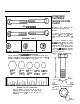
STANDARD FASTENER IDENTIFICATION CHART HEX CAPSCREW CARRIAGE Hardware sizes given in the illustrations throughout this manual. If a washer or nut is identified as “washer, l/2” or “nut, i/2”, this means the inside diameter is l/2 inch BOLT Q .~,@--: PLAIN WASHER LOCKWASHER @ NUT If a screw is identified as “screw, i/2 x 2”, this means the shaft diameter is l/2 inch and the shaft of the screw is 2 inches long.
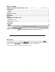
Table of Contents Inside Front Cover STANDARD FASTENER IDENTIFICATION CHART ...................................................... SAFETY RULES General ..................................................................................................................................................... 2 Preparation ............................................................................................................................................... 2 Operation ........................................
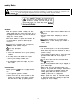
safety Rules Read these safety rules and follow them closely. Failure to obey these rules could result in loss of control of vehicle, severe personal injury to yourself or bystanders, or damage to property or equipment. The in the text signifies important cautions or warnings which must be followed. ALL WARNING, CAUTION, and instructional messages on this attachment and on your tractor should be carefully read and obeyed.
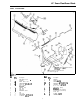
42” Snow Plow/Dozer Blade PARTS ILLUSTRATION / _ .ySpring location fir garden tractors ,(see chart on page 6). Spring location for lawn tractors (see chart on page 6). gurei. Rd. NO. A B C D E F G H I J K L M N Qtv. 1 1 1 2 1 2 4 1 1 1 4 4 2 2 Description Ref. NO. QW. Description BAR ASSY., Push SPRING 0 P 1 1 SPRING CHAIN, 4-Link CAPSCREW, 5/16-18x l-114 WASHER, Flat, 5116 LOCKNUT. Hex. 5116-18 I GUIDE ASSY., Rod Q 1 SETSCREW, 5/1&18x 112 ROD. Lift R S 2 1 COLLR.
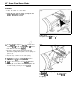
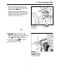
42” Snow Plow/Dozer Blade ASSEMBLY 1. Place the blade on a flat surface. 2. install two bar stops (A, figure 2) using the two 5/l 6-l 8 x 1” taptite’screws (B). Figure 2. Bar Stop A. Bar Stop B. Taptite Screw, 5/l 6-l 8 x 1 3: Insert eyebolt (A, figure 3) thru.iug on blade and screw on 5/16 nut (B) only far enough so that it is flush with the end of the eyebolt. 4. Hook the spring (C) into the pivot frame (D). Stretch the spring with a pliers to hook springs on eyebok (A). 5.
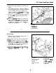
42” Snow Plow/Dozer Blade 8. Assemble the chain (A, figure 4) to the tractor as follows: a. On left-hand side, remove the upper self-tapping screw that holds bumper to frame. This is the hole used for installing chain in the following steps, using one 5/16-18x l-114 capscrew (B), two 5/16 washers (D), and one 5/16 locknut. b. Place one 5/16 washer onto the screw. Then place the chain on the capscrew, and then the other 5/16 washer. c. Insert the capscrew (B, figure 4) as shown.
42” Snow Plow/Dozer Blade 5. Raise the push bar and hook up the spring (A, figure 6) in location B or C as follows: Location I Tractor (Series) B 4000,5000,500,600, 12LT. 12RT. Resent C 6000,800, 16GTH, 17GTH I I 6. Lower the push bar and tighten the capscrew and nut which hold chain to tractor frame. gure 6.
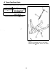
42” Snow Plow/Dozer Blade 7. Insert front of push bar (A, figure 7) into pivot frame on rear of blade. Then install king pin (C) down thru holes in hitch and pivot frame. Secure king pin (C) with spring clip (D). 8. Using king pin as the pivot, swivel push bar to align holes for pivot pin (E). Then install pivot pin downward thru holes in blade and push bar. The pivot pin can be installed in any of three holes, depending on desired blade angle. I Figure 7. Dozer Blade Assembled and Installed A.
42” Snow Plow/Dozer Blade REMOVAL 1. Lower the blade, 2. Remove blade and lii rod from push bar. 3. Raise push bar and unhook the spring (A, figure 6) from the chain. 4. Disconnect the lift rod from the lift lever on tractor by removing the spring clip. 5. Remove the bracket (J, figure 5) from the tractor hitch by removing four pins and safety clips. 6. Reinstall all pins (king pin, pivot pin, clevis pins) and secure with spring or safety clip for storage.
42” Snow Plow/Dozer Blade Normal Care After dozing jobs, hose down the blade to remove excess dirt. Coat bare metal surfaces to prevent rusting. Lightly oil all pivot points. If the wear plate (A, figure 9) on the bottom of the 42” blade is worn excessively, replace it wrth a new one by removing the six carriage bolts (B), lo&washers (C) and nuts (D). igure 9. ,. Wear Plate .
42” Snow Plow/Dozer Blade Skid Shoes Alternate holes are provided to permit adjustment of the shoe assemblies for raising and lowering the blade to various working heights (see figure 11). When cleaning snow from gravel or earth drives or walks the shoe assemblies should be lowered fully to prevent blade contact with gravel or ground. When cleaning smooth hard surfaces, like concrete, the shoe assemblies are normally placed fully up to allow the blade to scrape the surface.
42” Snow Plow/Dozer Blade NOTES 11
42” Snow Plow/Dozer Blade NOTES 12
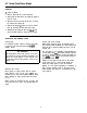
TORQUE SPECIFICATIONS FOR STANDARD MACHINE HARDWARE TOLERANCE 4096 SEE SAE GRADE R 0 h/Lb. FtJLbs. a-32 8-38 lo-24 lo-32 w-20 114-28 S/18-18 5118-24 318-18 318-24 7118-14 7118-20 l/2-13 l/2-20 9118-12 9118-18 5/a-ii 518-18 314-10 314-18 7/a-9 7/8-14 l-a 1-12 19 20 27 31 88 78 -7T 12 20 2 35 50 55 85 75 90 loo 180 180 140 155 220 240 SAEGRADE#5 SAEGRADEII) Q N m . 2.1 2.3 3.1 3.5 7.8 8.8 15. 18.3 27.2 31.3 40.8 47.8 as. 74.8 88.4 102. 122.4 138. 217.8 244.8 190.4 210.8 299.2 328.4 In./Lbs. FtJLbs.
SIMPLICITY MANUFACTURING, 500 N. Spring Street Port Washington, Wi 53074 INC. FORM 1709932 PRINTED IN U.S.A.