M A N U FAC T U R I N G , I N C. Intermediate Frame Snowthrowers Initial setup This Dealer Setup Instruction covers the following products: Intermediate Frame Snowthrowers Mfg. No.
Intermediate Frame Snowthrowers SAFETY RULES Read these safety rules and follow them closely. Failure to obey these rules could result in loss of control of unit, severe personal injury or death to you, or bystanders, or damage to property or equipment. The triangle in text signifies important cautions or warnings which must be followed. GENERAL OPERATION operate the unit safely enough to protect themselves and others from injury.
Intermediate Frame Snowthrowers Table of Contents Unpacking . . . . . . . . . . . . . . . . . . . . . . . . . . . . . . . . . . . . . . . . . . . . . . 4 1. Uncrate . . . . . . . . . . . . . . . . . . . . . . . . . . . . . . . . . . . . . . . . . . . . . . . . . . 4 2. Check Tire Pressure . . . . . . . . . . . . . . . . . . . . . . . . . . . . . . . . . . . . . . . . 4 3. Install Handles . . . . . . . . . . . . . . . . . . . . . . . . . . . . . . . . . . . . . . . . . . . . 5 4. Secure Dash . . . . . . . .
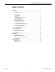
Intermediate Frame Snowthrowers 1 (2) x 2 TP 300-4681-01-IW-SN Size PSI bar 15 x 5.0-6 20 1,38 16 x 4.
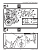
Intermediate Frame Snowthrowers 3 B D A B C A D A C 5/16-18 5/16-18 x 2 B D 5/16-18 x 2-3/4 5/16 4 7 Nm 5 lb-ft 09/2007 5 TP 300-4681-01-IW-SN
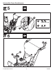
Intermediate Frame Snowthrowers 5 B A 5/16-18 x 1-1/2 B 5/16-18 A 6 A D C B TP 300-4681-01-IW-SN 6 09/2007
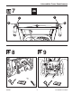
Intermediate Frame Snowthrowers 7 1 1 2 2 3 8 09/2007 9 7 TP 300-4681-01-IW-SN
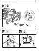
Intermediate Frame Snowthrowers 10 11 TP 300-4681-01-IW-SN 12 8 09/2007
Intermediate Frame Snowthrowers 09/2007 13 14 15 16 9 TP 300-4681-01-IW-SN
Intermediate Frame Snowthrowers Perform Safety Checks F E B A Check Engine Controls C 1. Make sure all safety guards are in place and all nuts, bolts, clips, cotter pins and wires are secure. 2. Check to make sure spark plug wire is attached. 3. Check all controls for proper operation: D a. The engine should stop when the key is removed. b. The throttle should control the engine speed and stop the engine when moved to the STOP position. G c.
Intermediate Frame Snowthrowers Perform Safety Checks E Check Snowthrower Controls 1. Check the skid shoes to make sure they are set at the desired height. Adjust if necessary. 2. Check the traction drive control (B, Figure 2). Snowthrower motion should stop when the control is released. B C 3. Check the auger control (C). Auger movement should stop when the control is released. 4. Check the manual chute direction control (D) for proper operation.
Intermediate Frame Snowthrowers Auger Drive Adjustment A D WARNING E Do not over-tighten, as this may lift the lever and cause auger drive to be engaged without depressing the Auger Control. F 1.With the drive lever released, the hook (B, Figure 3) should barely touch the lever (C) without raising it. There can be a maximum 1/32” clearance as shown. 2. To adjust, loosen nut (D) by holding the adjusting flats (A) and turning nut (D). Turn adjustment flats and hold screw.
Intermediate Frame Snowthrowers Run-In Adjustment WARNING ALL MODELS Do not over-tighten, as this may cause traction drive to engage without depressing the traction drive control (arm must remain in down position). 1. After 5 hours of use, check for proper adjustment. Readjust clutch cable if necessary by increasing tension on cable. A small amount of arm movement is permissible if unit passes operating checks described in the Warning above.
Intermediate Frame Snowthrowers 7. Loosen shift lever nuts (B, Figure 6), and position the shift speed lever (A) in the lowest forward speed. A B Figure 6. Shift Lever Adjustment A. Shift Lever B. Nuts, 1/4-20 8. Note the position of the friction wheel (A, Figure 7). The correct distance from the right side of the friction wheel to the outside of the frame is 4-5/16” (10.95 cm). If the friction wheel is not in the correct position, adjust as follows. 9.
Intermediate Frame Snowthrowers Belt Adjustment Auger Drive Belt B If your snowthrower will not discharge snow, check the control cable adjustment. If it is correct, then check the condition of the auger drive belt. If it is damaged or loose,replace it (see Belt Replacement in this section of the manual). 1. Disconnect spark plug wire. 2. Loosen screw (B, Figure 9) from belt cover (A). Remove belt cover (A). B 3.
Intermediate Frame Snowthrowers Belt Replacement A B F Auger Drive Belt The drive belts are of special construction and must be replaced with original factory replacement belts available from your nearest authorized service center. Some steps require the assistance of a second person. If the auger drive belt is damaged, the snow thrower will not discharge snow. Replace the damaged belt as follows. C L D K E 1. Disconnect the spark plug wire. A 2.
Intermediate Frame Snowthrowers B A A Figure 14. Rotator Shaft Removal A. Pin, Hair B. Shaft A C Figure 16. Chute and Rotator Removal A. Chute and Rotator B D A Figure 15. Offset Tube (Lower) Removal A. Nuts, KEPS, hex, 5/16-18 B. Bolts, Carriage, 5/16 x 1-1/2 C. Tube, Offset D. Bracket, tube support B 9. Remove hair pin (A, Figure 14) and slide rod (B) backward about 3 inches (until shaft separates from the worm drive). D 10.
Intermediate Frame Snowthrowers Traction Drive Belt If the snow thrower will not move forward, check the traction drive belt for wear or damage. If the traction drive belt is worn or damaged, replace the belt as follows. 1. Disconnect the spark plug wire. 2. Remove the auger drive belt. See “Belt Replacement” in this section. 3. Remove the traction drive spring (E, Figure 12). B 4. Remove the e-ring (J, Figure 12) from one end of the swing plate axle rod (I). 5.