
Technical information


2/8
1SDC210033D0202
Ekip LS/I
Main characteristics:
Q available for XT2 and XT4 in the three-pole and four-pole versions;
Q protections:
– against overload (L): 0.4...1xIn adjustable protection threshold, with adjustable time trip curve;
– against short-circuit with delay (S): 1...10xIn adjustable protection threshold, with adjustable
time trip curve (as an alternative to I protection);
– against instantaneous short-circuit (I): 1...10xIn adjustable protection threshold, with instan-
taneous trip curve (as an alternative to S protection);
– of the neutral in four-pole circuit-breakers:
- for In *100A can be selected in the OFF or ON positions, 50%, 100% of the phases;
- for In <100A, neutral protection is fi xed at 100% of the phases and disableded by user;
Q manual setting using the relative dip-switches on the front of the trip unit, which allow the set-
tings to be made even when the trip unit is off;
Q LED:
– LED with steady green light indicating that the trip unit is supplied correctly. The LED comes
on when the current exceeds 0.2xIn;
– red LED for each protection:
- L: LED with steady red light, indicates pre-alarm for current exceeding 0.9xI
1
;
- L: LED with fl ashing red light, indicates alarm for current exceeding setted threshold;
- LS/I: LED with steady red light, shows that the protection has tripped. After the circuit-
breaker has opened, connect the Ekip TT or Ekip T&P accessory to fi nd out which protec-
tion function tripped the trip unit;
– Ekip LS/I is equipped with a trip coil disconnection detection device that detects whether the
opening solenoid has disconnected. Signalling is made by all the red LEDs fl ashing simulta-
neously;
Q test connector on the front of the release:
– to connect the Ekip TT trip test unit, which allows trip test, LED test and signalling about
latest trip happened;
– to connect the Ekip T&P unit, which allows the measurements to be read, the trip test to be
conducted and the protection functions test to be carried out;
Q thermal memory which can be activated by Ekip T&P;
Q self-supply from 0.2xIn minimum current up.
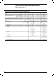
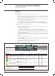
Ekip LS/I
Protection function Trip threshold Trip curve
(1)
Excludability Relation Thermal memory
Against overloads with
long inverse time delay trip
according to IEC 60947-2
Standard
Manual setting:
I
1
= 0.4...1xIn step 0.04
Tolerance: trip between
1.05…1.3 I
1
(IEC 60947-2)
Manual setting:
t
1
= 12-36s at I=3xI
1
Tolerance: ±10% up to 4xIn
±20% from 4xIn
– t = k/l
2
Yes
Against short-circuits with
indipendend time delay
(t=k)
Manual setting:
I
2
= 1-1.5-2-2.5-3-3.5-4.5-5.5-
6.5-7-7.5-8-8.5-9-10xIn
Tolerance: ±10%
t
2
= 0.1-0.2s
Tolerance: ±15%
Yes t = k –
Against short-circuits with
adjustable treshold and
instantaneous trip time
Manual setting:
I
3
= 1-1.5-2-2.5-3-3.5-4.5-5.5-
6.5-7-7.5-8-8.5-9-10xIn
Tolerance: ±10%
)20ms Yes t = k –
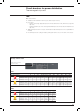
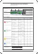
Circuit-breakers for power distribution
Electronic trip units
L, S, I protection LED
Test Connector
Dip switch for LS/I
protection function setting
Power-on LED
Dip switch for the trip curve selection
Dip switch for the selection
between S protection function
or I protection function
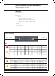
(1)
Tollerances in case of:
– self-powered trip unit at full power;
– 2 or 3 phase power supply.
In conditions other than those considered, the
following tollerance hold:
Protection Trip threshold Trip time
L
release between 1.05 and 1.3 x I
1
±20%
S
±10% ±20%
I
±15% )60ms
Slot for lead seal