
Technical information

6/10
1SDC21099DF0001
1SDC210033D0202
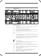
Wiring Diagrams of the accessories
Motor operator
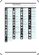
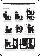
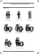
Description of Figures
Fig. 21 =
Direct control motor operator (MOD) (only for XT1 and XT3 fixed or plug-in circuit-breakers) (see
note I).
Fig. 22 = Motor operator with stored energy (MOE) (only for circuit-breakers XT2 and XT4).
Fig. 23 = A contact for electrical signalling of stored energy motor operator that can be operated remotely.
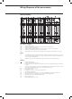
Notes
F) Additional external resistor for MOD and MOE supplied at 480/525V AC.
Caption
= Diagram figure number
* = See the note indicated by the letter
A17 = Actuator unit type MOE for the stored energy motor operator
H2 = Signalling lamp for stored energy motor operator blocked
J.. = Connectors for the auxiliary contacts of the withdrawable version circuit-breaker; extraction of the
connectors takes place at the same time as that of the circuit-breaker
M = Motor with excitation in series for opening and closing the circuit-breaker (fig. 21)
M = Motor for opening the circuit-breaker and spring charging for closing the circuit-breaker (fig. 22)
M1 = Three-phase asynchronous motor
R1 = Resistor (see note F)
S1 = Contact controlled by the cam of the motor operator
S2 = Contact controlled by the key lock of the motor operator with direct action
S3/1-2 = Contacts controlled by the Auto/Manual selector and key lock of the stored energy motor operator
S4 = Contact controlled by the cam of the motor operator with direct action
S6/1-2 = Contacts controlled by the Auto/Manual selector of the motor operator with direct action
SC = Pushbutton or contact for closing the circuit-breaker
SO = Pushbutton or contact for opening the circuit-breaker
V2 = Motor operator applications
V4 = Indicative apparatus and connections for control and signalling, outside the circuit-breaker
XD.. = Nine-way connector for the auxiliary circuits of the plug-in version circuit-breaker
XV = Terminal boxes of the circuit-breaker applications
YC = Shunt closing release of the stored energy motor operator