
Technical information


6/11
1SDC21000EF0001
1SDC210033D0202
Signalling contacts
Description of Figures
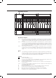
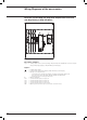
Fig. 31 = One changeover contact for electrical signalling of circuit-breaker open or closed and one changeover
contact for electrical signalling of circuit-breaker open due to tripping of the magnetic, thermomagnetic
or electronic trip units, YO, YO1, YO2, YU (tripped position) (only for voltages up to 250V) (see notes
E and I).
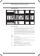
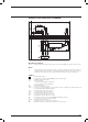
Fig. 32 = Two changeover contacts for electrical signalling of circuit-breaker open or closed, two changeover
contacts for electrical signalling of circuit-breaker open due to tripping of the magnetic, thermomag-
netic or electronic trip units, YO, YO1, YO2, YU (tripped position) and one changeover contact for
electrical signalling of circuit-breaker open due to tripping of the thermomagnetic or electronic trip
unit (only for voltages up to 250V).
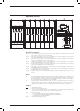
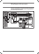
Fig. 33 = Three changeover contacts for electrical signalling of circuit-breaker open or closed and two
changeover contacts for electrical signalling of circuit-breaker open due to tripping of the magnetic,
thermomagnetic or electronic trip units, YO, YO1, YO2, YU (tripped position) (only for voltages up to
250V).
Notes
E) The 24V auxiliary power supply unit of fig. 48 must necessarily be installed in the circuit-breaker seats
marked SY/1 and Q/2. Therefore, should you want to install the unit in fig. 48 and the contacts in fig.
31 at the same time, the contacts of fig. 31 must be installed in the adjacent slots; that is, contact
SY/1 in the slot marked SY/2 and contact Q/2 in the slot marked Q/1.
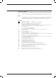
Caption
= Diagram figure number
* = See the note indicated by the letter
J.. = Connectors for the auxiliary contacts of the withdrawable version circuit-breaker; extraction of the
connectors takes place at the same time as that of the circuit-breaker
Q/0..3 = Circuit-breaker auxiliary contacts
S51 = Contact for electrical signalling of circuit-breaker open due to tripping of the thermomagnetic or
electronic trip unit
SY/1..2 = Contacts for electrical signalling of circuit-breaker open due to tripping of the thermomagnetic trip
units, YO, YO1, YO2, YU (tripped position)
V1 = Circuit-breaker applications
V4 = Indicative apparatus and connections for control and signalling, outside the circuit-breaker
XC.. = Six-way connector for the plug-in version circuit-breaker auxiliary contacts
XD.. = Nine-way connector for the auxiliary circuits of the plug-in version circuit-breaker
XE.. = Fifteen-way connector for the auxiliary circuits of the plug-in version circuit-breaker
XV = Terminal boxes of the circuit-breaker applications