
Technical information


6/13
1SDC21002EF0001
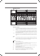
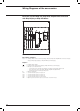
104 102 114 112 124 122 134 132 142 144 152 154
104
102
114
112
124
122
134
132
142
144
152
154
101
111 121 131 141 151
101
111
121
131
141
151
1SDC210033D0202
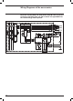
Signalling contacts
Description of Figures
Fig. 39 = Three supplementary changeover contacts for electrical signalling of circuit-breaker open or closed
(only for fixed or plug-in version circuit-breakers).
Fig. 41 = First changeover position contact of the circuit-breaker, for electrical signalling of connected (only
for plug-in or withdrawable version circuit-breakers).
Fig. 42 = Second changeover position contact of the circuit-breaker, for electrical signalling of connected (only
for plug-in or withdrawable version circuit-breakers).
Fig. 43 = Third changeover position contact of the circuit-breaker, for electrical signalling of connected(only
for plug-in or withdrawable version circuit-breakers).
Fig. 44 = Fourth changeover position contact of the circuit-breaker, for electrical signalling of connected (only
for plug-in or withdrawable version circuit-breakers).
Fig. 45 = First changeover position contact of the circuit-breaker, for electrical signalling of isolated (only for
withdrawable version circuit-breakers).
Fig. 46 = Second changeover position contact of the circuit-breaker, for electrical signalling of isolated (only
for withdrawable version circuit-breakers).
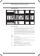
Fig. 48 = Auxiliary circuits of the 24V auxiliary power supply unit and of the HMI030 type interface unit (see
note E).
Notes
E) The 24V auxiliary power supply unit of fig. 48 must necessarily be installed in the circuit-breaker seats
marked SY/1 and Q/2. Therefore, should you want to install the unit in fig. 48 and the contacts in fig. 31
at the same time, the contacts of fig. 31 must be installed in the adjacent slots; that is, contact SY/1 in
the slot marked SY/2 and contact Q/2 in the slot marked Q/1.
H) Having requested a Uaux insulated from earth, one must use “galvanically separated converters” in
compliance with IEC 60950 (UL 1950) or equivalent standards that ensure a common mode current or
leakage current (see IEC 478/1, CEI 22/3) no greater than 3.5 mA, IEC 60364-41 and CEI 64-8.
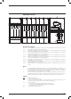
Caption
= Diagram figure number
* = See the note indicated by the letter
J.. = Connectors for the auxiliary contacts of the withdrawable version circuit-breaker; extraction of the
connectors takes place at the same time as that of the circuit-breaker
K51 = Electronic trip unit:
– of overcurrent type Ekip LS/I, Ekip N-LS/I, Ekip LSI, Ekip LSIG
– of motor protection type Ekip I, Ekip M-I, Ekip M-LIU, Ekip M-LRIU
– of generator protection type Ekip G-LSI
Q/0..7 = Circuit-breaker auxiliary contacts