
Technical information


6/15
1SDC21074GF0001
1SDC210033D0202
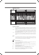
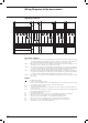
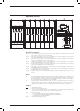
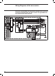
Electronic trip unit Ekip E-LSIG connected with Ekip Display
or Ekip LED Meter
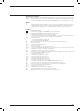
Description of Figures
Fig. 50 = Auxiliary circuits of the Ekip E-LSIG microprocessor-based release connected to the Ekip Display
(display) or Ekip LED Meter (current display) display unit.
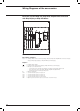
Caption
= Reference number of diagram figure
A11 = Display unit type Ekip Display (display) or Ekip LED Meter (current display)
K51 = Microprocessor-based release:
– overcurrent release type Ekip LS/I, Ekip N-LS/I, Ekip LSI, Ekip LSIG, Ekip E-LSIG
– motor protection release type Ekip I, Ekip M-I, Ekip M-LIU, Ekip M-LRIU
– generator protection release type Ekip G-LSI
Q = Main switch
TI/L1 = Current transformer located on phase L1
TI/L2 = Current transformer located on phase L2
TI/L3 = Current transformer located on phase L3
TI/N = Current transformer located on neutral
YO1 = Opening solenoid of microprocessor-based overcurrent release