
Technical information


6/17
1SDC21004EF0001
1SDC210033D0202
Auxiliary circuit of Ekip-Com and HMI030
Description of Figures
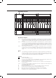
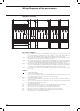
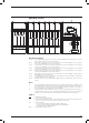
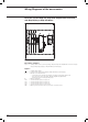
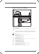
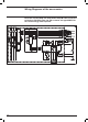
Fig. 52 =
Auxiliary circuits of the Ekip Com type interface unit and of the HMI030 type interface unit (see note E).
Notes
H) Having requested a Uaux insulated from earth, one must use “galvanically separated converters” in
compliance with IEC 60950 (UL 1950) or equivalent standards that ensure a common mode current or
leakage current (see IEC 478/1, CEI 22/3) no greater than 3.5 mA, IEC 60364-41 and CEI 64-8.
Caption
= Diagram figure number
A12 = Interface unit type Ekip Com (with MODBUS serial communication)
A13 = Signalling unit type LD030 DO
K51 = Electronic trip unit:
– of overcurrent type Ekip LSI, Ekip LSIG
– of motor protection type Ekip M-LRIU
Q = Main circuit-breaker
Q/0..7 = Circuit-breaker auxiliary contacts
SY/1..3 = Contacts for electrical signalling of circuit-breaker open due to tripping of the thermomagnetic trip
units, YO, YO1, YO2, YU (tripped position)
TI/L1 = Current transformer placed on phase L1
TI/L2 = Current transformer placed on phase L2
TI/L3 = Current transformer placed on phase L3
TI/N = Current transformer placed on the neutral
WI = Serial interface with the trip unit accessories
WS = Serial interface with the control system (MODBUS EIA RS485 interface)
XF = Connector of the Interface unit type Ekip Com
XG-XH = Electronic trip unit connectors
XV = Terminal boxes of the circuit-breaker applications
YO1 = Opening solenoid of the microprocessor-based overcurrent release