
Technical information


6/21
1SDC21077GF0001
1SDC210033D0202
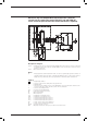
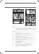
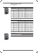
Electronic trip unit Ekip M-LRIU connected to the contactor
control unit for starting the motor PR212/CI and with ABB AF
series contactor (the circuit to the motor thermistor is optional)
Description of Figures
Fig. 55 = Auxiliary circuits of the electronic trip unit type Ekip M-LRIU connected to the contactor control unit
for starting the motor type PR212/CI and with ABB AF series contactor (the circuit to the motor
thermistor is optional).
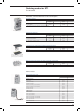
Fig. 62 = Motor thermistor circuit.
Notes
H) Having requested a Uaux insulated from earth, one must use “galvanically separated converters” in
compliance with IEC 60950 (UL 1950) or equivalent standards that ensure a common mode current or
leakage current (see IEC 478/1, CEI 22/3) no greater than 3.5 mA, IEC 60364-41 and CEI 64-8.
Caption
= Diagram figure number
A15 = Contactor control unit for starting the motor type PR212/CI
H1 = Signalling lamp
J.. = Connectors for the auxiliary contacts of the withdrawable version circuit-breaker; extraction of the
connectors takes place at the same time as that of the circuit-breaker
K = Contactor for starting the motor
K51 = Electronic trip unit Ekip M-LRIU
M1 = Three-phase asynchronous motor
Q = Main circuit-breaker
R2 = Motor thermistor
SC3 = Pushbutton for starting the motor
SO3 = Pushbutton for stopping the motor
TI/L1 = Current transformer placed on phase L1
TI/L2 = Current transformer placed on phase L2
TI/L3 = Current transformer placed on phase L3
X42 = Circuit connector for the motor thermistor
X5 = Circuit connector towards PR212/CI unit
XG-XH = Electronic trip unit connectors
YO1 = Opening solenoid of the microprocessor-based overcurrent release