
Technical information


2/10
1SDC210033D0202
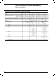
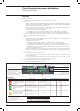
Ekip LSI – Ekip LSIG
Protection function Trip threshold Trip curve
(1)
Excludability Relation Thermal
memory
Against overloads with
long inverse time delay trip
according to IEC 60947-2
Standard
Manual setting:
I
1
= 0.4...1xIn step 0.02
Tolerance: trip between
1.05…1.3 I
1
(IEC 60947-2)
Manual setting:
t
1
= 3-12-36-60s
at I=3xI
1
Tolerance: ±10% up to 4xIn
±20% from 4xIn
– t = k/l
2
Yes
Electronic setting:
I
1
= 0.4...1xIn step 0.01
Tolerance: trip between
1.05…1.3 I
1
(IEC 60947-2)
Electronic setting:
t
1
= 3...60s
at I=3xI
1
step 0.5
Tolerance: ±10% up to 4xIn
±20% from 4xIn
– t = k/l
2
Yes
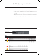
Against short-circuits
with inverse short (t=k/I
2
)
or indipendent (t=k) time
delay trip
Manual setting:
I
2
= 1-1.5-2-2.5-3-3.5-4.5-5.5-
6.5-7-7.5-8-8.5-9-10xIn
Tolerance: ±10%
Manual setting:
t
2
= 0.05-0.10-0.20-0.40s
at 10xIn
Tolerance: ±10% up to 4xIn
±20% from 4xIn
Yes t = k/l
2
–
Electronic setting:
I
2
= 1...10xIn step 0.1
Tolerance: ±10%
Electronic setting:
t
2
= 0.05...0.40s
at 10xIn step 0.01
Tolerance: ±10% up to 4xIn
±20% from 4xIn
Yes t = k/l
2
–
Manual setting:
I
2
= 1-1.5-2-2.5-3-3.5-4.5-5.5-
6.5-7-7.5-8-8.5-9-10xIn
Tolerance: ±10%
Manual setting:
t
2
= 0.05-0.1-0.2-0.4s
Tolerance: ±15% t
2
>100ms
±20% t
2
)100ms
Yes t = k –
Electronic setting:
I
2
= 1...10xIn step 0.1
Tolerance: ±10%
Electronic setting:
t
2
= 0.05...0.4s step 0.01
Tolerance: ±15% t
2
>100ms
±20% t
2
)100ms
Yes t = k –
Against short-circuits with
adjustable threshold and
instantaneous trip time
Manual setting:
I
3
= 1-1.5-2-2.5-3-3.5-4.5-5.5-
6.5-7-7.5-8-8.5-9-10xIn
Tolerance: ±20%
)40ms Yes t = k –
Electronic setting:
I
3
= 1...10xIn step 0.1
Tolerance: ±10%
)40ms Yes t = k –
Against earth fault with
independent time delay
trip
(2)
Manual setting:
I
4
= 0.2-0.25-0.45-0.55-0.75-
0.8-1xIn
Tolerance: ±10%
Manual setting:
t
4
= 0.1-0.2-0.4-0.8s
Tolerance: ±15%
Yes I
2
t = k –
Electronic setting:
I
4
= 0.2...1xIn step 0.02
Tolerance: ±10%
Electronic setting:
t
4
= 0.1...0.8s step 0.05
Tolerance: ±15%
Yes I
2
t = k –
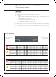
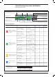
Circuit-breakers for power distribution
Electronic trip units
L, S, I, G protection LED
Test connector
Dip switch for the S trip
curves selection
Power-on LED
Dip switch for LSIG
protection function setting
Dip switch for the trip curve selection
Selection for remote
or local setting
Selection for manual or
electronic setting
(1)
Tollerances in case of:
– self-powered trip unit at full power;
– 2 or 3 phase power supply.
In conditions other than those considered,
the following tollerance hold:
Protection Trip threshold Trip time
L
release between 1.05 and 1.3 x I
1
±20%
S
±10% ±20%
I
±15% )60ms
G
±15% ±20%
Slot for lead seal
(2)
Protection G is inhibited for currents higher than 2 In.