OPERATOR’S MANUAL Axion / 150Z Series 18.5, 21, 24, 26HP Zero-Turn Riders Mfg. No. Description 7800360 7800380 7800269 7800392 7800374 7800381 7800378 7800386 7800393 7800390 7800379 7800391 7800375 7800382 7800387 7800394 Simplicity Axion Model ZT18533, 18.5HP w/ 33” Mower Simplicity Axion Model CZT18533, 18.5HP w/ 33” Mower (California Model) Snapper 150Z Model SC18533, 18.5HP w/ 33” Mower Snapper 150Z Model CSC18533, 18.
TABLE OF CONTENTS Safety Rules General Operation...................................................2 Transportation & Storage ........................................2 Slope Operation ......................................................3 Towed Equipment....................................................3 Children...................................................................3 Emissions................................................................3 Ignition System ...................................
SAFETY RULES Read these safety rules and follow them closely. Failure to obey these rules could result in loss of control of unit, severe personal injury or death to you, or bystanders, or damage to property or equipment. This mowing deck is capable of amputating hands and feet and throwing objects. The triangle in text signifies important cautions or warnings which must be followed. GENERAL OPERATION 19. Follow the manufacturer’s recommendations for wheel weights or counterweights. 20.
SLOPE OPERATION WARNING Slopes are a major factor related to loss-of-control and tipover accidents, which can result in severe injury or death. Operation on all slopes requires extra caution. If you cannot back up the slope or if you feel uneasy on it, do not operate on it. Control of a walk-behind or ride-on machine sliding on a slope will not be regained by the application of the brake.
4 1. Fold this page along dotted line indicated above. 2. Hold page before you so that its left edge is vertically parallel to a tree trunk or other upright structure. 3. Sight across the fold in the direction of hill slope you want to measure. 4. Compare the angle of the fold with the slope of the hill. WARNING: To avoid serious injury, operate your unit up and down the face of slopes, never across the face. Do not operate on slopes greater than 10 degrees.
SERVICE AND MAINTENANCE 13. If the fuel tank must be drained, it should be drained outdoors. 14. Replace faulty silencers/mufflers. 15. Maintain or replace safety and instruction labels as necessary. 16. Use only authorized replacement parts when making repairs. 17. Always comply with factory specifications on all settings and adjustments. 18. Only authorized service locations should be utilized for major service and repair requirements. 19.
SAFETY & OPERATION DECALS All DANGER, WARNING, CAUTION and instructional messages on your rider and mower should be carefully read and obeyed. Personal bodily injury can result when these instructions are not followed. The information is for your safety and it is important! The safety decals below are on your rider and mower. This unit has been designed and manufactured to provide you with the safety and reliability you would expect from an industry leader in outdoor power equipment manufacturing.
IDENTIFICATION NUMBERS SA M PL E ID Tag When contacting the service center for replacement parts, service, or information you MUST have these numbers. Record your model name/number, manufacturer’s identification numbers, and engine serial numbers in the space provided for easy access. The identification tag is located on the underside of the seat. Tilt the seat forward to access the ID tag.
OPERATION Left Ground Speed Control Lever Right Ground Speed Control Lever Ground Speed Levers - Ground Speed Levers DRIVE Positons START/PARK Positons Mower Cutting Height Switch Parking Brake Lever Choke (Closed) Choke (Open) Parking Brake Lever ENGAGE Positon Parking Brake Lever DISENGAGE Positon Fuel Tank Cap Engine Speed (Fast) CONTROL FUNCTIONS The information below briefly describes the function of individual controls.
Choke Hour Meter The hour meter measures the number of hours the key has been in the RUN position. CLOSE the choke for cold starting (pull knob up). OPEN the choke once the engine starts (push knob down). If the engine is warm, it may not require choking. If this is the case, set the choke to OPEN (push the knob down) while cranking the engine. In most cases, you will need to close the choke in order to start the engine.
CHECKS BEFORE STARTING • Check that the crankcase oil is filled to full mark on dipstick (see CHECK ENGINE OIL in the Maintenance section). • Fill the fuel tank with fresh fuel. FUEL RECOMMENDATIONS For daily operation: Use only unleaded gasoline with a pump sticker octane rating of 87 or higher. Gasohol (up to 10% ethyl alcohol, 90% unleaded gasoline by volume) is approved as a fuel.
EMERGENCY STOPPING 9. Stop the rider and engine (see STOPPING THE RIDER AND ENGINE). In the event of an emergency the engine can be stopped by simply turning the ignition switch to STOP. Use this method only in emergency situations. For normal engine shut down follow the procedure given in STOPPING THE RIDER AND ENGINE. PUSHING THE RIDER BY HAND NOTE: Do not disengage the transmissions if parked on a slope. 1.
DRIVING PRACTICE - Smooth Travel BASIC DRIVING The lever controls of the zero turn rider are highly responsive. WARNING: Never operate on slopes greater than 17.6% (10°). See SLOPE OPERATION in the safety section. Zero turn riders operate differently from other fourwheeled vehicles. The drive wheels are also your steering wheels. If you cannot drive the unit on a hill, you will not be able to steer the unit on it. Operating zero turn units on slopes requires extra caution.
Practice Turning Around a Corner Practice Turning In Place While traveling forward allow one handle to gradually return back toward neutral. Practice several times before mowing. To “zero turn” means to turn in place. To turn in place, gradually move one ground speed control lever forward from neutral and one lever back from neutral simultaneously. Repeat several times.
MOWER DECK REMOVAL & INSTALLATION - 33” DECKS A B C NOTE: Perform mower removal and installation on a hard, level surface such as a concrete floor. WARNING A After lowering the mower cutting height, engage parking brake, turn off the mower blades, turn the ignition switch to STOP, and remove key before attempting to install or remove the mower. Removing the Mower Deck 1.
MOWER DECK REMOVAL & INSTALLATION - 42” & 50” DECKS B A C NOTE: Perform mower removal and installation on a hard, level surface such as a concrete floor. WARNING After lowering the mower cutting height, engage parking brake, turn off the mower blades, turn the ignition switch to STOP, and remove key before attempting to install or remove the mower. D Removing the Mower Deck 1.
MAINTENANCE MAINTENANCE SCHEDULE The following schedules should be followed for normal care of your rider and mower.
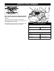
Rider Maintenance Items WARNING Move the ground speed levers to START/PARK positions, engage the parking brake, turn the mower blades OFF, turn the ignition switch OFF, and wait for all moving parts to stop before accessing the engine compartment or performing any maintenance procedures. ACCESSING THE ENGINE COMPARTMENT Figure 14. Accessing the Engine Compartment Lift up on the back edge of the seat deck to access the engine compartment.
LUBRICATION Service Interval: 25 hours. Lubricate the unit at the locations shown in Figures 17 through 23 as well as the following lubrication points. Grease: • front wheel grease fittings • front wheel bushings • mower pivots • mower arbors Use grease fittings when present. Not all greases are compatible. Use automotive-type lithium grease. Figure 18.
Figure 23. Lubricating Mower Lift Figure 21. Lubricating Rider Figure 22.
CLEAN DECK & CHECK / REPLACE MOWER BLADES Service Interval: 25 hours or as required. WARNING For your personal safety, do not handle the sharp mower blades with bare hands. Careless or improper handling of blades may result in serious injury. WARNING Figure 24. Blade Removal - 33” Deck For your personal safety, blade mounting hardware must each be installed as per instructions. Torque blade mounting hardware to torque noted in instructions. 1.
B C A E D D A C B Figure 29. Blade Installation - 50” Deck A. 4x4 Wood Block B. Hex Washer C. Spring Washer D. Blade Capscrew E. Lift Wings Figure 27. Blade Installation - 33” Deck A. Blade B. Blade Mounting Bolts C. Lockwashers D. Hex Nuts A D B C Figure 28. Blade Installation - 42” Deck A. 4x4 Wood Block C. Blade Nut B. Spring Washers D.
CLEAN THE BATTERY AND CABLES CHECK RIDER SAFETY SYSTEM Service Interval: 100 Hours WARNING Service Interval: Every 100 hours, every spring/fall, and after storage of 30 days or longer. Be careful when handling the battery. Avoid spilling electrolyte. Keep flames and sparks away from the battery. When removing or installing battery cables, disconnect the negative cable FIRST and reconnect it LAST. If not done in this order, the positive terminal can be shorted to the frame by a tool.
CHECK / ADJUST PTO CLUTCH A WARNING B To avoid serious injury, perform adjustments only with engine stopped, key removed and tractor on level ground. Service Interval: 200 Hours. B The Power Take Off (PTO) clutch drives the mower blades. The PTO clutch is engaged and disengaged by the mower blade switch. Check the PTO clutch adjustment every 200 hours of operation. Also perform the following procedure if the clutch is slipping, will not engage, or if a new clutch has been installed. B Figure 31.
Engine Maintenance Items Use oil classified API Service Class SF, SG, SH, SJ or better with SAE Viscosity: CHECK ENGINE OIL LEVEL 30 Conventional** Service Interval: Before each use, and every 8 hours. 5W-30 10W-30 Conventional* 1. Turn the engine off, and set the parking brake lever to ENGAGE. 2. Clean the area around the dip stick (C, Figure 34). Synthetic 5W-30, 10W-30 3. Remove the dip stick (C) and clean it with a paper towel.
SERVICE AIR FILTER & PRE-CLEANER - 18.5 & 21 HP ENGINES A B NOTE: Air filter configuration may differ from shown. Consult engine manual for further information. Interval: Pre-Cleaner: Every 25 hours or as required. Air Filter: Every 50 hours or as required. A B Replacement Interval: Pre-Cleaner: As required. Air Filter: Every 200 hours or once per season. 1. Air Filter Removal & Installation 1. Lift up on the bottom of the latch (A, Figure 35 or 36) and flip the latch away from the cover. A 2.
A A Figure 37. Air Filter Cover A. Air Filter Cover Screws Figure 38. Air Filter Removal A. Filter Cartridge SERVICE AIR FILTER 24 & 26HP ENGINES A NOTE: Air filter configuration may differ from shown. Consult engine manual for further information. Service Interval: Every 25 hours or as required. 1. Loosen the air filter cover screws (A, Figure 37) and remove the air filter cover. 2. Locate the air filter cartridge (A, Figure 38). Pull up on the front edge of the cartridge until it snaps out of place.
Pre-Cleaner Service Pre-Cleaner Air Filter NOTE: Replace a worn or damaged pre-cleaner. 1. Figure 40. Wash the pre-cleaner in liquid detergent and water. 1. 1. 2. 2. 2. Squeeze the pre-cleaner dry and saturate with engine oil. Remove all excess oil by squeezing the pre-cleaner in an absorbent cloth. Air Filter Service NOTE: Replace a worn or damaged air filter. 1. Figure 40. If stamped “Washable,” the filter can be washed with warm water and mild soap. Figure 40. Air Filter Service 2.
SERVICE & ADJUSTMENTS GROUND SPEED CONTROL LEVER ADJUSTMENT C The control levers have three adjustments: To Adjust Control Lever Height: Pull the levers in across the operator’s lap to their DRIVE positions. Loosen the mount bolts (D, Figure 42) and raise or lower the levers to the desired position. Tighten the mounting bolts.(D). A D To Adjust Control Lever End Gap: The control lever end gap (C, Figure 43) should be adjusted so that the levers do not contact each other when placed in DRIVE positions.
BRAKE ADJUSTMENT 1. Stop the unit, turn the ignition OFF, set the ground speed levers to START/PARK positions, set the parking brake lever to the ENGAGE position, and wait for all moving parts to stop. 3" (7.62cm) 2. Locate the brake rod (A, Figure 44) and adjustment nut (B). D 3. Measure the parking brake spring. Its compressed length, with the parking brake lever in the ENGAGE position, should be 3” (7.62cm). Adjust the spring length by turning the adjustment nut (B), if necessary.
MOWER DECK LEVELING ADJUSTMENTS A B WARNING Before inspecting or adjusting the mower, turn the mower blades OFF, turn the ignition switch OFF, and allow all moving parts to stop. Remove ignition key, then disconnect the spark plug wire and fasten it away from the spark plug. C Figure 45. Measure Blade Tips to Ground A. Mower Deck B. Blade Tip C. Level Ground Side to Side Leveling - 33” Decks If the cut is uneven, the mower may need leveling.
MOWER DECK LEVELING ADJUSTMENTS A B WARNING Before adjusting the mower, turn the mower blades OFF, turn the ignition switch OFF, remove the key, and allow all moving parts to stop. Disconnect the spark plug wire and fasten it away from the spark plug. C Figure 48. Measure Blade Tips to Ground A. Mower Deck B. Blade Tip C. Level Ground Side to Side Leveling - 42” & 50” Decks If the cut is uneven, the mower may need leveling. Unequal or improper tire pressure may also cause an uneven cut.
A B Figure 51. Orient Blades Front-to-Back Front To Back Leveling - 33” Deck If the cut is uneven, the mower may need leveling. Unequal or improper tire pressure may also cause an uneven cut. See CHECK TIRE PRESSURE. Figure 52. Front-to-Back Leveling A. Hitch Rod B. Jam Nuts (hidden from view) 1. Turn the blade front-to-back as shown in Figure 51. Measure the distance from the ground to front tip of blade, and from ground to rear tip of blade (Figures 51).
C 42” Deck B A Figure 54. Front-to-Back Leveling A. Hitch Rod B. Rear Jam Nut C. Front Jam Nut 50” Deck Figure 53. Orient Blades Front-to-Back Front To Back Leveling - 42” & 50” Decks If the cut is uneven, the mower may need leveling. Unequal or improper tire pressure may also cause an uneven cut. See CHECK TIRE PRESSURE. 1. Turn the blades front-to-back as shown in Figure 53.
MOWER BELT REPLACEMENT B A WARNING Before inspecting or servicing the mower, turn the mower blades OFF, turn the ignition switch OFF, and allow all moving parts to stop. Remove ignition key, then disconnect the spark plug wire and fasten it away from the spark plug. C E D Mower Drive Belt Replacement - 33” Decks 1. Park the rider on a level surface. Disengage the PTO, turn off the engine, set the ground speed control levers to START/PARK, and set the parking brake lever to ENGAGE. Remove the key.
Mower Drive Belt Replacement - 50” Decks A 1. Park the rider on a level surface. Disengage the PTO, turn off the engine, set the ground speed control levers to START/PARK, and set the parking brake to ENGAGE. Remove the key. G F B 2. Use the idler pulley arm (K, Figure 57) to release belt tension and remove the mower drive belt (F) from the PTO pulley (G). E C D 3. Remove the belt from the remaining deck pulleys. Note: It is not necessary to remove the mower deck. 4.
TROUBLESHOOTING While normal care and regular maintenance will extend the life of your equipment, prolonged or constant use may eventually require that service be performed to allow it to continue operating properly. The troubleshooting guide below lists the most common problems, their causes and remedies. WARNING To avoid serious injury, perform maintenance on the rider or mower only when the engine is stopped, the ground speed levers are set to START/PARK, and the parking brake lever is set to ENGAGE.
Engine runs, but Transmission release levers in PUSH rider will not positions. drive. Drive belt slips. Move levers to DRIVE positions. Clean or replace belt as necessary. Belt is broken. Replace drive belt. Contact your local authorized dealer. Parking brake is not fully released. Contact your local authorized dealer. Parking brake will not hold. Rider steers or handles poorly. Parking brake is incorrectly adjusted. See Service & Adjustments Section. Improper tire inflation.
SPECIFICATIONS NOTE: Specifications are correct at time of printing and are subject to change without notice. ENGINE (18.5HP): CHASSIS: Make Model Horsepower Displacement Fuel Tank Cap. Rear Wheels Briggs & Stratton ELS 18.5 @ 3600 rpm 30.59 Cu. in (500cc) Front Wheels ENGINE (21HP): Make Model Horsepower Displacement TRANSMISSION: Briggs & Stratton ELS 21 @ 3600 rpm 30.59 Cu.
SERVICE ITEMS Replacement Parts Technical Manuals Replacement parts are available from your authorized dealer. Always use genuine Simplicity or Snapper Service Parts. Additional copies of this manual are available, as well as fully illustrated parts lists. These manuals show all of the product’s components in exploded views (3D illustrations which show the relationship of parts and how they go together) as well as part numbers and quantities used.
Lawn Care & Mowing Information HOW AND WHEN TO WATER, FERTILIZE & AERATE HOW TO WATER YOUR LAWN Most lawns are watered too often, but with too little water. However too much water can allow development of diseases with your lawn. It is best to water the lawn only when necessary, and then to water it slowly, evenly, and deeply—imitating a slow, soaking rain. HOW TO FERTILIZE YOUR LAWN The best method of watering a lawn is to imitate a slow, soaking rain, applying about 1 inch of water.
Lawn Care & Mowing Information WHEN AND HOW OFTEN TO MOW The time of day and condition of the grass greatly affect the results you’ll get when mowing. For the best results, follow these guidelines: G Mow when the grass is between 3”-4” (7,5-10 cm) high. G Mow with sharp blades. Short clippings of grass one inch or shorter decompose more quickly than longer blades. Sharp mower blades cut grass cleanly and efficiently, preventing frayed edges which harm the grass.
M A N U FA C T U R I N G , I N C . 500 N Spring Street / PO Box 997 Port Washington, WI 53074-0997 PRODUCTS, INC. 535 Macon Street McDonough, GA 30253 www.SimplicityMfg.com www.Snapper.com Briggs & Stratton Yard Power Products Group Copyright © 2008 Briggs & Stratton Corporation Milwaukee, WI USA.