© SIMPLIPHI POWER, INC.
SimpliPhi Your Energy Security and Independence and gain control of your own power. SimpliPhi Power helps you manage your power as a personal resource. Anytime. Anywhere. SimpliPhi energy storage optimizes integration of any power generation source – solar, wind, generator – on or off grid, and protects your home and mission-critical business functions from power outages and intermittency. SimpliPhi storage technology reduces operating temperature constraints, toxic coolants and the risk of thermal runaway.
Table of Contents 1.0 – Important Safety Information ................................................................................................................................ 4 1.1 – Safety Instructions ...................................................................................................................................... 4 1.2 – Safety & Protective Features........................................................................................................................... 5 1.
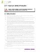
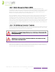
1.0 – Important Safety Information CAUTION: THESE 14 THINGS WILL VOID THE PHI WARRANTY & DAMAGE THE BATTERIES. READ IN FULL PRIOR TO BATTERY INSTALLATION 1.1 – Safety Instructions 1. Before using the unit, read all instructions and cautionary markings on the unit, the PHI 3.8 Batteries, and all appropriate sections of this manual. 2. PHI 3.8 Batteries must be fully charged before commissioning the AccESS unit (i.e. before turning on connected loads). Failure to do so will Void the Warranty. 3.
13. The AccESS unit does not have any user-serviceable parts. Do not disassemble the inverter except where noted for connecting wiring and cabling. See your Warranty for instructions on obtaining service. Attempting to service the components inside the AccESS unit yourself may result in a risk of electrical shock or fire and Void the Warranty. Internal capacitors remain charged after all power is disconnected – wait 10 minutes before servicing. 14.
CAUTION: Verify polarity at all connections with a standard voltmeter before 1) energizing the system and 2) turning the PHI 3.8 80 Amp breaker “ON/OFF” switch to the “ON” position. Reverse polarity at the battery terminals will Void the Warranty and destroy the PHI 3.8 Batteries. PHI 3.8 Batteries pose some risk of shock or sparking during the installation and initial wiring and connection process. This is consistent with all other battery-based storage formats.
1.2.3 – Battery Management System (BMS) The PHI 3.8 Batteries within the AccESS unit are manufactured utilizing Lithium Ferrous Phosphate (LFP) cells, which are produced under exclusive patented licensed technologies, as well as proprietary materials, architecture, manufacturing processes and battery management system (BMS). This assures the highest grade and quality, longest cycle-life, greatest efficiency and freedom from material impurities, toxicity and hazardous risk. Each PHI 3.
1.3 – Limitations of Use The Conext XW Pro or XW+ Inverter/Charger built into the SimpliPhi Power AccESS is not intended for use in connection with life support systems or other medical equipment or devices. 1.4 – Inverter/Charger Programming Settings The Schneider Electric Conext XW Pro Inverter/Charger and XW+ Inverter/Charger has a firmware limitation that creates a potential issue with Lithium-Ion batteries: The Low Battery Cut-Out Voltage (LBCO) setting is limited to 48V maximum.
2.0 – Product Description 2.1 – Overview The SimpliPhi AccESS offers industry leading renewable energy storage technology to provide energy security and power resiliency into a pre-assembled, pre-programmed system that is suitable for installation inside and outside. The AccESS serves all of the common residential scale renewable energy applications: Off-Grid, Grid-Tied with Battery Back Up, Self-Consumption – with Zero Export, Time of Use (TOU) Arbitrage and Peak Load Shaving for utility charge reduction.
Table 1.0 – AccESS Specifications SPECIFICATIONS AccESS 1.0 (x3 PHI 3.8) AccESS 2.0 (x4 PHI 3.8) General Dimensions Weight Enclosure Rating 29.5” W x 76”H (w/feet) x 20” D / 75 cm W x 193 cm H (w/feet) x 51 cm D 600 lbs. (272.16 kg.) without batteries 834.72 lbs. (378.62 kg.) with batteries 600 lbs. (272.16 kg.) without batteries 912.96 lbs. (414.11 kg.
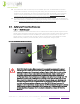
2.3 – Inside the AccESS NEMA-3R Rated Cabinet The AccESS system is enclosed within a NEMA-3R rated cabinet. Within, the internal layout provides easy access to clearly labeled wiring points and includes the necessary overcurrent devices, breakers and disconnects. See Figures 2.0 & 3.0 below for detail. Figure 2.0 – AccESS Unit Components The heart of the AccESS is the SimpliPhi Power PHI 3.8 kWh 48V 60A power storage modules. The power storage is modular and expandable. The base level energy storage is 11.
2.3.1 – AccESS Core Components The core components within the AccESS unit include the below listed products. See Figures 2.0 & 3.0 for detail. • Schneider Electric Conext XW Pro NA or XW+ 6848 NA o o 6.8 kW Continuous Output 120/240 V AC 12 kW AC Peak Output – 60 Seconds • Conext Mini PDP • (3) or (4) PHI 3.8 kWh Batteries (11.4 or 15.2 kWh) • Conext System Control Panel (SCP) o Single point of control and set up for all connected Conext devices.
(SCP) or Conext ComBox to engage a generator and can assist an inverter/charger when output power demands are high. Note: Refer to Section 4.5.2 regarding the additional required “either-or” interlocked switch for AC Coupled systems that include a generator. • Cellular Modem Allows remote monitoring of the system without utilizing a land-based internet connection. 3.0 – Pre-Installation The information within this section covers pre-installation procedures & considerations, namely, PHI 3.
3.2 – System Sizing for Your Installation The number of PHI 3.8 Batteries within the AccESS unit should be specified in terms of total storage capacity before the initial installation based on the goals and objectives of the project. All PHI 3.8 Batteries are balanced during final production and testing stages. Following proper wiring guidelines ensures that a system will not require any manual balancing processes. CAUTION: Do not combine PHI 3.8 Batteries with other brands or chemistries.
Figure 3.0 – AccESS Unit Dimensions SimpliPhi Power, Inc. | 3100 Camino Del Sol | Oxnard, CA 93030, USA | (805) 640-6700 | info@simpliphipower.com| SimpliPhiPower.
3.5 – Clearance Requirements The AccESS should be installed with 3-inch (7.62 cm) clearance to the sides and 3 feet (0.91 m) clearance to the front to allow for the cabinet door to be opened during installation. Please see Figure 4.0 for details. All installations should comply with local code requirements and/or the local AHJ, which may exceed the requirements shown. Figure 4.0 – AccESS Unit Clearances SimpliPhi Power, Inc.
3.6 – Knock Out Locations Three 1.375-inch OD knockouts and one 2-inch OD knockout are located on both sides of the AccESS cabinet. They can be used for AC or DC inputs. Not all knockouts must be used. Figure 5.0 – AccESS Cabinet Knock-Outs (sides) SimpliPhi Power, Inc. | 3100 Camino Del Sol | Oxnard, CA 93030, USA | (805) 640-6700 | info@simpliphipower.com| SimpliPhiPower.
3.7 – Pad Mounting 3.7.1 – Pad Requirements The AccESS must be installed and secured on level concrete. For a pre-cast concrete pad, a 4” minimum thickness is required. The pad should be 3” wider than the AccESS on all sides (34” x 22” x 4”). The AccESS is not suited for wall mounting. Any attempt to wall mount the AccESS unit will Void the Warranty. 3.7.
4.0 – Installation & Wiring This section covers how to install the PHI 3.8 Batteries within the AccESS unit, torque values, communications and network preparation and how to wire the AccESS unit. It also provides guidance on how to install optional AccESS unit components/accessories. 4.1 – Basic System Configuration Concepts Safe and reliable installation requires trained and certified technicians. The following discussion is a basic primer.
4.5 – Wiring the AccESS 4.5.1 – Wiring Diagrams Please reference the below listed DC coupling and AC coupling diagrams, where applicable. DC Coupled System 11.4 kWh, 5.7 kW (3) PHI 3.8 BATTERIES SimpliPhi Power, Inc. | 3100 Camino Del Sol | Oxnard, CA 93030, USA | (805) 640-6700 | info@simpliphipower.com| SimpliPhiPower.
AC Coupled System 11.4 kWh, 5.7 kW (3) PHI 3.8 BATTERIES CAUTION: Confirm the coupled grid-tie inverter’s compatibility with Schneider’s Conext XW Pro or Conext XW+ prior to installation. SimpliPhi Power, Inc. | 3100 Camino Del Sol | Oxnard, CA 93030, USA | (805) 640-6700 | info@simpliphipower.com| SimpliPhiPower.
4.5.2 – Making AC Connections AC Landing Points – Terminal Blocks The SimpliPhi AccESS is equipped with multiple knockouts on either side of the AccESS for accessibility to the AC connections. All AC connections are at 240 V. Please refer to Schneider Electric’s Conext XW Pro or Conext XW+ Installation Manual for 120 V installations. The Mini PDP has landing points for: • • AC IN: grid input AC OUT: home subpanel, optional AC coupled PV Figure 7.
CAUTION: On the Conext Mini PDP, an additional circuit breaker will need to be installed. The Generator will connect through this circuit breaker and to the XW Pro or XW+ 6848 inverter. CAUTION: In an AC Coupled system configuration, an “either-or” interlocked switch must be installed between the generator output and the inverter’s AC2 (gen) input. Failure to install this additional switch creates the potential for power to back feed from the grid-tie inverter to the generator.
Inverter Charger Grounding The Conext XW Pro or XW+ is provided with ground terminals that must be reliably connected to ground (protective earth) by appropriately sized equipment grounding conductors. System grounding for the AC and DC systems must be done according to all applicable NEC and local installation codes. Feed-in Protection Requirements The amount of power that can be fed into a distribution panel and the means and location for feed-in, must be in accordance with NEC 2017 article 690.
4.5.4 – Making DC Connections This section only applies to AccESS systems equipped with the optional Conext MPPT 80 600 Solar Charge Controller. Refer to the Conext MPPT 80 600 Owner’s Guide for further information regarding functionality programming of the charge controller. Note: Before connecting PV, verify the cable polarity and mark the cable accordingly as Positive or Negative. The SimpliPhi AccESS is equipped with multiple knock outs.
Note: if a grounded DC system is required, ensure that the system bonding is done in one location only, and that all conductors and connections comply with all applicable NEC and local installation codes. 4.5.5 – Basic Functional Test The following procedure should be followed once the installation is complete and before it is put into service. Step 1: Confirm All Connections After the AC and DC wiring has been installed and connected, check that all connections are correct and secure.
Figure 11.0 – Inverter Disabled Display To enable the inverter: On the inverter information panel, simultaneously press the STARTUP/ SHUTDOWN button and the Equalize button. The Conext XW Pro or XW+ is now enabled, and “En” (enabled) is briefly displayed on the inverter information panel Figure 12.0 – Inverter Enabled Display To disable the inverter: On the inverter information panel, simultaneously press the STARTUP/ SHUTDOWN button and the Equalize button.
Figure 13.0 – Inverter Disabled Display Monitor the invert (green kW) LED to confirm which mode the inverter is in: • kW LED OFF – Invert mode is disabled. The inverter/charger is not powering the AC loads. However, if good AC is present, it is passed through to the loads. • “Sch” displayed on the inverter information panel – The inverter/charger is in search mode and is looking for an AC load greater than the Search Watts setting (default = 25 watts).
Figure 14.0 – Inverter AC Load Display Confirming Battery Charger Operation 7. Apply AC from grid or generator. LEDs will blink while the power source is qualified. 8. Check LEDs (AC1 or AC2) on the front panel. One of them must be ON for the unit to charge. 9. Check the amp (A) LED. If the A LED is ON, the unit is charging and the PHI 3.8 Battery current is displayed on the inverter information panel. Figure 15.0 – Inverter Charge Rate Display This completes the functional test.
If purchased with the Conext Gateway or ComBox option, please refer to the Conext Gateway or ComBox Owner’s Guide from Schneider Electric. Network Requirements Before making AC and DC connections, route communication cables through the raceways. For easier identification, use a different color for each communications cable, or cable tags. Connect communications cables to their components after AC and DC connections are made. 4.6.
− The Schneider Electric Owner’s Guide contains information and procedures necessary for configuring, operating, maintaining, and troubleshooting the Schneider Electric Conext XW Pro or XW+ Inverter/Charger. The guide is intended for anyone who needs to operate, configure, and troubleshoot the inverter. Certain configuration tasks should only be performed by qualified personnel. 5.3 – Operating Parameters Per Warranty Although the PHI 3.
Table 3.0 – Programming Settings for SimpliPhi PHI 3.8 kWh 48V Battery w/Schneider Electric Inverter XW Pro or XW+ 6848 INVERTER – XW Pro or XW+ 6848 10K Cycles Warranty 5K Cycles Warranty 3.5K Cycles Warranty Advanced Settings > Inverter Settings 80% DoD 48V (50.5V Recommended) 90% DoD 48V (49.8V Recommended) 2.
Table 4.0 – Programming Settings for SimpliPhi PHI 3.
Inverter Programming Settings for an AC Coupled System In an AC Coupled system, the only recommended system setup is a Grid-Tie with Battery Backup application. During normal system operation, this setup allows for the coupled grid-tie inverter(s) to power the home’s loads and sell excess energy to the grid, while the batteries typically remain fully charged.
Enable Grid Support in the inverter’s Setup menu and set Grid Support Volts (GSV) in the inverter’s Advanced Settings > Grid Support menu to the desired voltage. For instance, a GSV value of 50.6V allows the battery to discharge to roughly 20% State of Charge before the Conext inverter connects to the grid to assist in powering local loads. Refer to Table 7.0 for a complete set of voltages correlated with States of Charge.
5.3.3 – Battery Monitor Table 5.0 – Programming Settings for SimpliPhi PHI 3.8 kWh 48V Battery w/Schneider Electric Conext Battery Monitor Conext Battery Monitor 10K Cycles Warranty Advanced Settings Capacity2 Discharge Rate Nominal Temp Shunt Amps Shunt mV Self Disch Discharge Floor Float Voltage Float Amps Auto Sync Time Temp Unit Back Light Timer Peukert Expo Charge Eff Mode Temp Coeff Default Temp Sync Sensitivity Time Rem Filter 5K Cycles Warranty 80% DoD 90% DoD 75Ah per PHI 3.
5.3.4 – PHI 3.8 Voltage Reference of Battery State of Charge Figure 16.0 and Table 4.0 below depict the typical voltage levels (VDC) for the PHI 3.8 Battery at various states of charge. Figure 16.0 – PHI 3.8 C/2 Discharge Curve (typical) Table 7.0 SOC Voltage 100% > 52.50 V 95% 51.70 V 90% 51.65 V 75% 51.40 V 50% 51.00 V 20% 50.20 V 10% 49.50 V 0% 48.00 V *Levels typical @ C/2 6.
Appendix A – Schneider Electric Product Specifications A.
Function 120 V/240 V 120 V Response Time Anti-islanding reconnect 254.4 V (± 3 V) 127.2 V (± 3 V) 300 s (+1/–0 s) Over frequency disconnect 60.5 Hz (± 0.05 Hz) 60.5 Hz (± 0.05 Hz) 60 ms (± 20 ms) Under frequency disconnect 59.3 Hz (± 0.05 Hz) 59.3 V (± 0.05 Hz) 60 ms (± 20 ms) Over voltage LN fast disconnect 135 V (± 1.5 V) 135 V (± 1.5 V) 60 ms (± 25 ms) Over voltage LN slow disconnect 132 V (± 1.5 V) 132 V (± 1.
A.4 – Schneider Electric Conext XW+ 6848 NA AC Overload Capability Figure 17.0 - Conext WX+ Operating Time vs 120VAC Load Graph A.5 – Schneider Electric Conext XW+ Output Power Versus Ambient Temperature When the internal temperature of the Conext XW+ exceeds a preset limit, it begins to limit output power automatically to stop maximum internal temperatures from being exceeded. Figure 18.0 - Conext WX+ Operating Temperature vs Load Graph SimpliPhi Power, Inc.
A.6 – Schneider Electric Conext XW+ Inverting Efficiency (Typical) Figure 19.0 - Conext WX+ Efficiency vs Load Graph A.7 – Schneider Electric Conext XW+ Charging Efficiency (Typical) Figure 20.0 - Conext WX+ Charge Efficiency vs Current Graph A.8 – Schneider Electric Conext XW+ Charging Power Factor Figure 21.0 - Conext WX+ Charging Power Factor vs Current Graph SimpliPhi Power, Inc. | 3100 Camino Del Sol | Oxnard, CA 93030, USA | (805) 640-6700 | info@simpliphipower.com| SimpliPhiPower.