Sol-Ark Integration Guide AmpliPHI 3.8 kWh Batteries SimpliPhi Power, Inc. | 3100 Camino Del Sol | Oxnard, CA 93030, USA | (805) 640-6700 | info@simpliphipower.com | SimpliPhiPower.
SimpliPhi Your Energy Security and Independence and gain control of your own power. SimpliPhi Power helps you manage your power as a personal resource. Anytime. Anywhere. SimpliPhi energy storage optimizes integration of any power generation source – solar, wind, generator – on or off grid, and protects your home and mission-critical business functions from power outages and intermittency.
Table of Contents 1.0 – Introduction .......................................................................................................................... 4 2.0 – Battery Bank-to-Inverter Connection ................................................................................ 4 3.0 – Battery Bank Sizing .............................................................................................................. 7 3.1 – All Systems ....................................................................
1.0 – Introduction This integration guide covers the recommended set up and configuration of Sol-Ark equipment for optimizing performance with SimpliPhi’s AmpliPHI batteries. CAUTION: THIS INTEGRATION GUIDE IS RELEVANT TO AMPLIPHI BATTERIES ONLY. REFER TO THE SOL-ARK INTEGRATION GUIDE FOR SIMPLIPHI POWER PHI BATTERIES, LINKED HERE, FOR APPLICATIONS USING CORE POWER PHI BATTERIES THAT DO NOT INCLUDE A NETWORKING COMMUNICATIONS PORT.
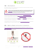
It is acceptable but not required to use the ferrite choke on the positive and negative DC busbar-to-inverter leads (see Figure 1 above). SimpliPhi and Sol-Ark recommend against using the 100 Ohm resistor included with the Sol-Ark equipment to charge the Sol-Ark’s capacitors when connecting the SimpliPhi Batteries for the first time (as described in the Sol-Ark Install Guide Owner’s Manual). Do not install the Battery Temperature Sensor. The SimpliPhi Batteries require no temperature compensation.
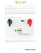
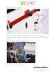
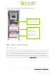
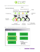
Figure 3: AmpliPHI’s Terminator Plug Utilizing the closest battery to the inverter, create the closed loop communications bridge between the AmpliPHI Battery and the Communication Input Port (labeled “CAN”) in the Sol-Ark Inverter utilizing CAT5 or greater cable. The cable length from the last AmpliPHI Battery in the chain to the Inverter cannot exceed 40m (131 feet). Figure 4: Sol-Ark’s Battery Networking Connection Port SimpliPhi Power, Inc.
Figure 5: AmpliPHI’s Networking Connections to Sol-Ark Equipment Battery bank-to-inverter networking connection Terminator plugs at either end of the battery “daisy-chain” bank-to-inverter networking connection 3.0 – Battery Bank Sizing 3.1 – All Systems AmpliPHI batteries in DC Coupled or AC Coupled systems should be sized according to the connected loads’ energy (kWh) and power (kW) requirements.
For example, one AmpliPHI battery has a maximum continuous discharge rate of 37.5 Amps DC. The AmpliPHI battery communicates this value to the Sol-Ark and auto-populates the Sol-Ark’s Max A Discharge parameter to this value. When 45 Amps DC (120% of 37.5 ADC) are discharged from the battery to the loads (equivalent to a ~9 Amps at 240 VAC load), then the system will shut down. AmpliPHI 3.8 Battery Rated kWh Capacity per Battery 3.8 kWh DC @ 100% DoD 3.
Homeowners with little to no loads on during the day (while solar power production is at its peak) might consider sizing a larger PHI battery bank to take advantage of the entire solar PV output potential for battery charging. Homeowners that consistently power loads during peak solar power production times may require a smaller sized battery bank. 4.
Figure 6: Sol-Ark Home Screen (Touchscreen), from the Sol-Ark Installation Manual Figure 7: Sol-Ark System Setup Screen, from the Sol-Ark Installation Manual SimpliPhi Power, Inc. | 3100 Camino Del Sol | Oxnard, CA 93030, USA | (805) 640-6700 | info@simpliphipower.com | SimpliPhiPower.
Checking the BMS Lithium Batt box in the Batt Setup menu’s “Batt” tab first will auto-populate all values communicated from the AmpliPHI batteries to the Sol-Ark (see Figure 8 below).
Table 1 – Sol-Ark Battery Settings for AmpliPHI Battery Models System Setup > Battery Setup > Batt Tab BMS Lithium Batt Batt Capacity Max A Charge1,2 Max A Discharge1 TEMPCO for your reference AmpliPHI Manually check this box BMS handles SOC determination. 75 Ah per AmpliPHI 3.8 battery No manual programming needed BMS auto-populates Max A Charge. ≤37.5 ADC per PHI 3.8 battery (Lower charge rates improve battery life) No manual programming needed. ≤37.5 ADC per PHI 3.
Batt Charge Efficiency 99% BMS handles SOC determination > Smart Load Tab Use Gen input as load output check this box if the Smart Load feature applies (refer to Section 5 of this Guide) Smart Load OFF Batt8 95% (51.7 V) 100% (52.5 V) Smart Load ON Batt9 For Micro inverter input Wattage value is used in grid-connected systems only. This value represents the minimum power required of the solar array before the Smart Loads are powered.
CAUTION: WHILE SOL-ARK SETTINGS MUST BE ADJUSTED WITH ANY CHANGE IN THE PAIRED QUANTITY OF STANDARD (NON-COMMUNICATIONS) PHI BATTERIES, AN INCREASE OR DECREASE IN THE NUMBER OF AMPLIPHI BATTERIES IN A BANK RESULTS IN AUTOMATICALLY ADJUSTED CAPACITY AND CHARGE/DISCHARGE CURRENT SETTINGS IN THE SOL-ARK EQUIPMENT. SIMPLIPHI ASKS THAT YOU CHECK THE ADJUSTED PARAMETERS’ VALUES HAVE AUTOMATICALLY UPDATED CORRECTLY. 4.
The power (W) column in Figure 4 above dictates the maximum amount of power pulled from the batteries and should be set to the AmpliPHI battery bank’s maximum discharge rate in AC Watts. To calculate the connected AmpliPHI battery bank’s maximum discharge Watts (AC): 1. Multiply the number of batteries in the bank by the maximum discharge rate (ADC) per battery 2. 3. a. AmpliPHI 3.8 battery max. discharge rate = 37.5 ADC per battery Convert the battery bank’s DC discharge current to DC discharge watts.
5.0 – Use Cases & Application Notes Sol-Ark equipment includes many advanced programming features and a variety of modes (more than one mode can be used simultaneously). This section of the Guide will outline the system programming and setup basics for common use cases. However, refer also to the Sol-Ark Manual for all installation requirements relevant to the application at hand.
5.1 – AC Coupled In an AC Coupled system setup, the grid-tie inverter(s) output – string or micro-inverters – is wired to the SolArk’s Generator Input (40A double-pole breaker) and the For Micro inverter input box in the Smart Load tab of the Battery Setup menu must be checked: Figure 10: Smart Load Tab in Batt Setup menu The Sol-Ark-8K is limited to a maximum of 7 kW of AC Coupled solar PV, and the Sol-Ark-12K is limited to 7.6 kW of AC Coupled solar.
A properly sized AmpliPHI battery bank based on the maximum draw of the critical loads sub-panel has a minimum of 4 batteries, even in this Grid-Tied with Battery Backup application. Note also that during a grid failure, the critical loads’ maximum energy draw (kWh) is also limited by the battery bank’s capacity. 5.
5.5 – Time of Use Selling / Energy Arbitrage Discharge batteries to power circuits during specific set times. Program these times to coincide with the utility company’s peak pricing times to avoid high energy charges from the utility.
5.6 – Off-Grid The Sol-Ark automatically operates in Off-Grid mode when it does not detect a grid connection. In an Off-Grid system setup, all the home’s loads are connected to the Sol-Ark’s Load Output (50A double-pole breaker). Do not use the Sol-Ark’s Grid Sell and Limited to Home modes in an off-grid system setup. Check the Limited power to load box in the Limiter tab of the Sol-Ark’s Grid Setup / Grid Param menu to allow for the batteries’ power to discharge to the connected loads. 5.
Figure 14 – Grid Input Tab in Grid Setup menu Homeowners who wish to include a grid connection, generator, and Smart Load functionality can install a transfer switch allowing for either grid or generator to connect to the Sol-Ark’s Grid Input. This frees up the Sol-Ark’s Generator Input to be used as an output for Smart Loads (see the following Smart Loads section for more details).
Power Technical Support (TechSupport@SimpliPhiPower.com) if the Smart Load feature will be used and battery bank sizing clarification according to Smart Load-specific loads needs to be clarified. Note that in a grid-connected system that utilizes the Smart Load feature, the Wattage value to the right of the Smart Load ON Batt parameter in the Smart Load menu tab (see Figure 5) represents the minimum power required of the solar PV array before the Smart Loads are powered.