©SIMPLIPHI POWER, INC.
SimpliPhi Your Energy Security and Independence and gain control of your own power. SimpliPhi Power helps you manage your power as a personal resource. Anytime. Anywhere. SimpliPhi energy storage optimizes integration of any power generation source – solar, wind, generator – on or off grid, and protects your home and mission-critical business functions from power outages and intermittency. SimpliPhi storage technology reduces operating temperature constraints, toxic coolants and the risk of thermal runaway.
Table of Contents 1.1 – Product Information & Online Resources .............................................................................................................. 4 1.2 – Technical Support ................................................................................................................................................ 5 2.0 – Testing .......................................................................................................................................................
1.0 – Introduction 1.1 – Product Information & Online Resources This Integration Guide covers the recommended set up and configuration of Outback Power equipment for optimizing performance with SimpliPhi PHI batteries. More information on SimpliPhi products can be found on our website: https://simpliphipower.com/. Specifically, the Product Documentation section of SimpliPhi’s web site (https://simpliphipower.
OutBack Power has instructional videos showing various steps of the battery commissioning and system programming process: http://www.outbackpower.com/resources/technical-support/videos. 1.2 – Technical Support SimpliPhi Technical Support (805-640-6700 x 1, techsupport@simpliphipower.com) is available to take any questions regarding this manual or general installation questions.
2.2.2 –OutBack Firmware Updates If needed, firmware updates for OutBack equipment can be downloaded at this link: http://www.outbackpower.com/resources-mobile/technical-support/firmware-updates. OutBack’s instructional video showing a firmware update in the MATE3 is posted here: https://www.youtube.com/watch?v=Cu81s-QFabY. 2.3 – Eliminating Battery Temperature Compensation The PHI Batteries’ charging regimen does not include any temperature compensation.
If the system includes DC Loads, no AC-to-DC conversion is necessary. Calculate the minimum quantity of PHI Batteries needed to ensure that the battery bank does not over-discharge by dividing the load rate by the MAX Continuous Discharge Rate per PHI Battery (found in Table 1.0 or on the relevant battery’s specification sheet).
In the case where the inverter’s AC Power Output rating exceeds the connected loads’ actual power draw (i.e. the inverter is rated at 5 kW but all loads amount to 3 kW of maximum instantaneous power draw), SimpliPhi still expects that the proper additional precautions be made to ensure that the PHI Battery bank is not overdischarged.
12V Inverter Model Inverter Power Rating (kW AC) Inverter Efficiency Load Rate (kW DC) PHI 1.4 - 12.8Vnom MIN Battery Quantity PHI 730 -12.8Vnom MIN Battery Quantity OutBack VFXR 2812A 2.8 90% 3.1 7 9 OutBack FXR 2012A 2 90% 2.2 5 7 3.2 – Sizing for Maximum Instantaneous Charge Rate (DC Coupled) In a DC Coupled system, the solar PV array output can be curtailed using charge controllers.
Example B: Two PHI 3.8 kWh-25.6Vnominal batteries (used in a 24-Volt system) must be paired with a 2,000-Watt solar PV array wired to a 100 Amp-rated charge controller. In this case, the 2,000-Watt solar array is used to determine the minimum PHI Battery quantity needed to prevent over-charging from the solar PV. 𝑊𝑊𝑊𝑊𝑊𝑊𝑊𝑊𝑊𝑊 = 𝐴𝐴𝐴𝐴𝐴𝐴𝐴𝐴 × 𝑉𝑉𝑉𝑉𝑉𝑉𝑉𝑉𝑉𝑉 2,000 𝑊𝑊𝑊𝑊𝑊𝑊𝑊𝑊 𝑆𝑆𝑆𝑆𝑆𝑆𝑆𝑆𝑆𝑆 𝑃𝑃𝑃𝑃 𝑎𝑎𝑎𝑎𝑎𝑎𝑎𝑎𝑎𝑎 = 𝐴𝐴𝐴𝐴𝐴𝐴𝐴𝐴 × 24 𝑉𝑉𝑉𝑉𝑉𝑉𝑉𝑉𝑉𝑉 2,000 𝑊𝑊𝑊𝑊𝑊𝑊𝑊𝑊𝑊𝑊 = 𝟖𝟖𝟖𝟖.
CAUTION: Not all grid-tie inverters (including micro-inverters) successfully AC Couple with battery-based inverters. Some grid-tie inverter manufacturers require specific updates to their equipment (via their Support staff) when configuring an AC Coupled system. Make sure to contact the relevant grid-tie inverter manufacturer regarding the feasibility of AC Coupling prior to an AC Coupled installation using OutBack equipment and SimpliPhi batteries.
Note also that the quantity of PHI Batteries calculated from this sizing guide is the minimum requirement to prevent over-discharge and over-charge from an instantaneous power perspective. The system may need more PHI Batteries in the battery bank in order to meet the system’s energy requirement (the amount of power the batteries must supply to the loads over time).
programming battery charging settings via the MATE3s are posted here: https://www.youtube.com/watch?v=RDsLpuSDG7o. (Note: This video shows inverter/charger programming; make sure to also program charge controller settings by selecting Charge Controller in the Settings menu.) The following Table outlines settings for the Radian and FXR/VFXR inverters, not the SkyBox. Table 1.
> Grid Zero Grid Zero DOD Volts Refer to Section 4.2.2 Grid Zero DOD Amps Inverter Settings > AC Input AC Input Select Priority Program this setting according to the homeowner’s system preference. Charger Operating Mode Program this setting according to the homeowner’s system preference. Charger AC Limit Refer to Section 4.2.3 > Grid Grid Input Mode Program this setting according to the homeowner’s system preference. Grid-Tie Program this setting according to the system’s setup.
batteries exceed the DoD Volts setting by 0.8 Vdc or more, the Radian will send power from the batteries to the loads. As the battery voltage decreases to the DoD Volts setting, the inverter will reduce the rate of flow toward zero and loads will be powered by the grid. It will maintain the batteries at this setting until renewable sources recharge the batteries.” Remember, the programmed Re-Bulk Voltage in the inverter is ignored while in Grid Zero mode because the inverter’s charger is off.
2. Apply the charger efficiency. If the charger converts AC Input power to DC Charging power at an 85% efficiency rate, then over 9,000 Watts AC can be used as the charger’s maximum AC Input. 7,680 𝑊𝑊𝑊𝑊𝑊𝑊𝑊𝑊𝑊𝑊 𝐷𝐷𝐷𝐷 = 9,035.3 𝑊𝑊𝑊𝑊𝑊𝑊𝑊𝑊𝑊𝑊 𝐴𝐴𝐴𝐴 0.85 3. Convert AC watts to AC current, by dividing AC watts by the inverter’s AC Voltage rating. The OutBack Radian has a 240VAC output rating, but some other OutBack inverters are rated at 120VAC. 9,035.3 𝑊𝑊𝑊𝑊𝑊𝑊𝑊𝑊𝑊𝑊 𝐴𝐴𝐴𝐴 = 𝟑𝟑𝟑𝟑.
PHI 2.7-25.6Vnom 45 1,152 1,355 5.6 11.3 PHI 2.6-25.6Vnom 45 1,152 1,355 5.6 11.3 PHI 1.4-25.6Vnom 28.5 730 858 3.6 7.2 PHI 1.3-25.6Vnom 26 666 783 3.3 6.5 PHI 1.4-12.8Vnom 45 576 678 2.8 5.6 PHI 1.3-12.8Vnom 40 512 602 2.5 5.0 PHI 730-25.6Vnom 14 358 422 1.8 3.5 PHI 675-25.6Vnom 13 333 392 1.6 3.3 PHI 730-12.8Vnom 28.5 365 429 1.8 3.6 PHI 675-12.8Vnom 26 333 392 1.6 3.3 4.
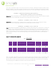
Table 3.0 – Settings for SimpliPhi PHI Battery w/ OutBack Charge Controller Charger 51.2Vnom PHI Battery 25.6Vnom PHI Battery 12.8Vnom PHI Battery Absorb Voltage1 56.4V 28.2V 14.1V Absorb Time 0.1 hour Float Voltage 54V 27V 13.5V ReBulk Voltage 51.2V 25.6V 12.8V DC Current Limit PHI battery banks sized according to Section 3.2 – Sizing for Maximum Instantaneous Charge Rate (DC Coupled) do not require any limitation of the charge controller’s DC Current output.
Absorb End Amps is disabled in the charge controller (set to 0). Note that in any OutBack system that includes a FNDC, the OutBack equipment will defer to the Return Amps setting in the FNDC rather than the Absorb End Amps setting in the FM100. In either situation, the low-current trigger setting is calculated by multiplying the nominal per-battery Amp-hour value times the number of batteries in the PHI Battery bank, times 0.
4.4 – FLEXnet DC Settings While the FLEXnet DC (FNDC) provides data logging of shunt information, it does not provide reliable State of Charge (SoC) measurements of the PHI Batteries when successive partial charging takes place at variable charge and discharge rates over many cycles. For this reason, using an FNDC in conjunction with PHI Batteries can frequently be misleading.
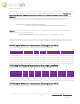
Table 6.0 – Battery Voltage VS. State of Charge (SOC) at C/2 Discharge Rate SOC 51.2Vnom PHI Battery 25.6Vnom PHI Battery 12.8Vnom PHI Battery 100% > 52.5 VDC > 26.25 VDC > 13.13 VDC 95% 51.7 VDC 25.9 VDC 12.93 90% 51.65 VDC 25.8 VDC 12.91 75% 51.4 VDC 25.7 VDC 12.85 50% 51.0 VDC 25.5 VDC 12.75 20% 50.2 VDC 25.1 VDC 12.55 10% 49.5 VDC 24.8 VDC 12.38 0% 48.0 VDC 24.0 VDC 12.0 4.5 – MATE3s Settings 4.5.
Table 8.
According to OutBack, the AGS’s 2 Minute Voltage Start is “considered an emergency start set point and … will start the generator regardless of Quiet Time settings.” Programming this parameter according to the settings listed in Table 8.0 above ensures that the battery does not discharge below ~80% Depth of Discharge.