Power. On Your Terms. PHI 3.8™, PHI 2.9™, PHI 1.4™ & PHI 730™ Battery Models INSTALLATION MANUAL INSTALLATION MANUAL Optimized Energy Storage & Management for Residential & Commercial Applications Utilizing Efficient, Safe, Non-Toxic, Energy Dense Lithium Ferrous Phosphate (LFP) Chemistry © SIMPLIPHI POWER, INC.
SimpliPhi Your Energy Security and Independence and gain control of your own power. SimpliPhi Power helps you manage your power as a personal resource. Anytime. Anywhere. SimpliPhi energy storage optimizes integration of any power generation source – solar, wind, generator – on or off grid, and protects your home and mission-critical business functions from power outages and intermittency.
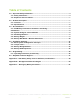
Table of Contents 1.0 – Important Safety Information ......................................................................................... 4 1.1 – Safety Instructions ...................................................................................................... 4 1.3 – Explosive Gas Precautions ......................................................................................... 7 2.0 – Product Description ......................................................................................
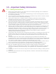
1.0 – Important Safety Information 1.1 – Safety Instructions 1. 2. 3. 4. 5. 6. 7. 8. 9. 10. 11. 12. 13. Before using the PHI Batteries, read all instructions and cautionary markings on the PHI Batteries, and all appropriate sections of this manual. PHI Batteries must be fully charged before commissioning (i.e. before connecting loads). Failure to do so will void the Warranty.
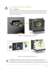
1.2 – Safety & Protective Features 1.2.1 – Breaker Each PHI battery with threaded stud connections is outfitted with a hydraulic/magnetic circuit breaker. This breaker increases safety during shipping and installations and allows the battery to effectively be turned “OFF” or “ON.” The breaker works in conjunction with the built-in battery management system (BMS) and creates additional safety, efficiency and functionality to the overall power storage system. Figure 1.0 - PHI 3.
determined by established standards and evaluated by certified electricians, licensed installers, and regional code authorities. Although each PHI Battery contains an internal BMS with circuitry that protects the Lithium Ferrous Phosphate cells from overcharge, over-discharge and extreme load amperage, the PHI Batteries must always be installed with a charge controller and the appropriate settings to protect the PHI Battery from open PV voltage and other high voltage charging sources.
Each PHI Battery contains circuitry that protects the Lithium Ferrous Phosphate cells from overcharge, over-discharge and extreme load amperage. If the values specified are exceeded, the protective circuitry will shut down the flow of electricity to/from the PHI Batteries. In some cases, this will result in the need to re-initialize an inverter charger. Often, inverter system settings will be saved within the inverter memory storage and will not need to be reset.
2.2 – Specifications Please review Table 1.0 below for PHI Battery specifications, including physical dimensions, Warranty period, and technical data. Table 1.0 - PHI Battery Specifications PHI 2.9™ PHI 3.8™ PHI 1.4™ PHI 730™ 24V 48V 24V 48V 24V 12V 24V 12V DC Voltages - Nominal 25.6 VDC 51.2 VDC 25.6 VDC 51.2 VDC 25.6 VDC 12.8 VDC 25.6 VDC 12.8 VDC Amp-Hours 151 Ah 75 Ah 115 Ah 57 Ah 57 Ah 115 Ah 28.5 Ah 57 Ah Rated Capacity @ C/2 3.8 kWh DC 3.8 kWh DC 2.9 kWh DC 2.
3.0 – Pre-Installation The information within this section covers pre-installation procedures & considerations, namely, PHI Battery performance parameters to be aware of during the design process, guidance on system sizing, as well as mounting hardware and PHI Battery weight to protect the PHI Battery and Warranty. 3.1 – PHI Battery Performance Parameters and Sizing Calculations PHI Batteries are designed to operate at a continuous C/2 rate across a large operating temperature range, as seen in Table 1.
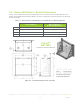
3.5 – Battery Wall Mount + Bracket Dimensions Please see the tables below for physical dimensions of the PHI 3.8 and PHI 2.9 Battery both with, and without, the SimpliPhi Power Mounting Bracket, as well as a diagram that provides guidance on Mounting Bracket assembly. Table 2.0 – Specifications: PHI 3.8 Battery v. PHI 3.8 Battery w/ Mounting Bracket PHI 3.8 Battery w/ Mounting Bracket PHI 3.8 Battery Width 13.5’’ 13.7” (18” with mounting flanges) Height 15.5’’ (including 1.5” terminal height) 15.
Table 3.0 – Specifications: PHI 2.9 Battery v. PHI 2.9 Battery w/ Mounting Bracket PHI 2.9 Battery w/ Mounting Bracket PHI 2.9 Battery Width 11.25’’ 13.7” (15.5” with mounting flanges) Height 12.75" (including 1.75” terminal height) 13” (including 1.75” terminal height) Depth 9.5” 10.5” Weight 61.06 Pounds 70.06 pounds Figure 3.0 – PHI 2.9 Mounting Bracket Assembly 4.
with you and your installation team to achieve a safe, reliable storage system that will provide years of maintenance free service. 4.1.1 – System Wiring Basics Refer to published electrical wiring specifications and ratings. All wire should be an appropriate gauge and construction to handle the loads that will be placed upon it. Heavy gauge, high strand copper wire is the industry standard due to its stability, efficiency and overall quality.
Figure 4.0 represents two PHI Batteries in Parallel. Wire lengths from PHI Batteries should be identical in length and gauge in order to balance the load across (all) PHI Batteries in the installation. Identical wiring length is a critical feature of parallel power storage systems that must be adhered to throughout all parallel wiring instructions. Failure to wire in parallel will void the Warranty. Special attention should be paid for parallel installations.
CAUTION: Do not reverse polarity. It will void the Warranty. Use a volt meter to check polarity before making connections to battery terminals or Anderson Connectors. A brief small spark is often present when connecting the second of two leads to a PHI Battery terminal. Example: If the Positive has been connected, a small spark will likely be present when connecting the Negative lead. This is a normal occurrence. Complete all connections in a clean, ventilated, well-lit area.
This allows a system to stay online until at least one full day of sun can recharge the PHI Battery bank. In any application, off-grid or grid-tied, if your PHI Battery bank is reaching the LBCO, load disconnects or load shedding set points may need to be adjusted. Refer to Programming section. In case of LBCO, cycle the DC Battery Disconnect (inverter), in order to reset the system.
5.0 – Programming 5.1 – Operating Parameters per Warranty Although the PHI Batteries are capable of performing at very high rates and depths of discharge within a very wide temperature range, in order to achieve extended life cycles and to comply with the Warranty, the operating parameters, indicated in Tables 4.0 and 5.0 below, must be applied based on desired Warranty/cycle life.
Although the PHI battery charges to the voltages outlined above, the battery “rests” at approximately 13.3V / 26.7V / 53.3V. Refer to Table 6.0 below for a complete Battery Voltage versus State of Charge (SOC) gauge. Table 6.0 – Battery Voltage VS. State of Charge (SOC) SOC 12V 24V 48V 100% > 13.13 VDC > 26.25 VDC > 52.5 VDC 95% 12.93 25.9 VDC 51.7 VDC 90% 12.91 25.8 VDC 51.65 VDC 75% 12.85 25.7 VDC 51.4 VDC 50% 12.75 25.5 VDC 51.0 VDC 20% 12.55 25.1 VDC 50.2 VDC 10% 12.38 24.
Appendix A – PHI Battery Safety & Green Attributes, Certifications This Appendix section covers the PHI Battery safety attributes and certifications, such as the lack of thermal runaway and off-gassing, UN DOT certification and UL compliance and certification. It also covers the PHI Battery’s green attributes – from products to materials to disposal, as well as relevant environmental and ecological considerations. B.1 – Safety Attributes and Certifications B.1.
B.2 – Green Attributes, Environmental & Ecological Considerations B.2.1 – Materials The primary materials (lithium, iron, phosphate) that make up PHI Batteries are environmentally benign and pose very few polluting or environmentally degrading by-products in the harvesting and refinement processes. This is especially true when compared to those of lead acid, NMC, NCA, LCO, NiCad, and NiMH batteries. B.2.
Appendix B – PHI Approved External Chargers This Appendix section covers the PHI Battery’s approved external / plug-in chargers. Typically, ancillary charging of SimpliPhi’s batteries is not required, and charging using any of the charge controllers and/or inverter/chargers listed in the “Integration Guides” section of the SimpliPhi web site’s Product Documentation page is acceptable. However, ancillary charging may be necessary in the following situations: 1.
Appendix C – PHI Legacy Battery Parameters SimpliPhi’s legacy batteries have previously been associated with different operating conditions and limitations than those outlined in Section 5.0 of this manual. While PHI Battery operation according to those previously published parameters is not harmful to the PHI Battery and does not void legacy batteries’ warranties, SimpliPhi recommends the following operating conditions for increased PHI Battery system optimization: Table C.