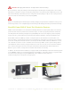
Power. On Your Terms. PHI2.6™ SMART-TECH BATTERY INSTALLATION MANUAL Optimized Energy Storage & Management for Residential & Commercial Applications Utilizing Efficient, Safe, Non-Toxic, Energy Dense Lithium Ferrous Phosphate (LFP) Chemistry. © SIMPLIPHI POWER, INC.
SimpliPhi Your Power Security and Independence and gain control of your own power. SimpliPhi helps you manage your power as a personal resource. Anytime. Anywhere. SimpliPhi energy storage optimizes integration of renewable power with the grid and protects your home and mission-critical business functions from power outages and intermittency. SimpliPhi storage technology eliminates operating temperature constraints, toxic coolants and the risk of thermal runaway and fire.
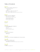
Table of Contents Page 4 PHI2.6™ Smart-Tech Battery Safety Protocol Safety & Protective Features • 80Amp Breaker • BMS PHI2.6™ Smart-Tech Battery Technical Overview PHI2.6™ Smart-Tech Battery Construction PHI2.
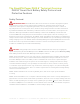
The SimpliPhi Power PHI2.6™ Technical Overview: PHI2.6™ Smart-Tech Battery Safety Protocol and Protective Features Safety Protocol: IMPORTANT NOTE: Circuit Breakers, Disconnects and Fuses should be employed throughout several points of a power storage and generation installation to effectively isolate and protect all components of the system to safeguard against faults, short circuits, polarity reversals or a failure of any component in the overall system.
CAUTION: Charging LFP batteries at temperatures below freezing. Do not attempt to charge the battery below 32 F (0 degrees C). Although cold temperatures do not harm PHI batteries, attempts to charge at subfreezing temperatures can adversely affect SOH and cycle life, and will void the Warranty. If the battery must be charged below 32 F (0 degrees C), the rate of charge must be at no more than 5% of the battery’s rated capacity (C/20).
SimpliPhi Power PHI2.6™ Smart-Tech Battery Performance Parameters and Sizing Calculations: PHI2.6™ Smart-Tech Batteries perform at full rated capacity in most operating environments. No increase in sizing, no special compensations, no burying procedure or insulation needs to be considered when determining the size of the energy storage and management system under the following circumstances and conditions.
Installation Procedure and Diagrams System Sizing for Your Installation The number of PHI2.6™ Smart-Tech Batteries should be specified in terms of total storage capacity before the initial installation based on the goals and objectives of the project. All PHI2.6™ Smart-Tech Batteries are balanced during final production and testing stages. Following proper wiring guidelines ensures that a system will not require any manual balancing processes. DO NOT COMBINE PHI2.
Figure 2.0 - PHI2.6™ 48 Volt, 2621 watt-hour (2.6kWh) Smart-Tech Batteries: Residential Installation PHI SMART-TECH BATTERIES ARE DESIGNED FOR PARALLEL OPERATION ONLY - DO NOT ARRANGE IN SERIES FOR INCREASED VOLTAGE System Wiring Basics Refer to published electrical wiring specifications and ratings. All wire should be an appropriate gauge and construction to handle the loads that will be placed upon it.
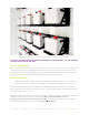
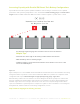
Simple Parallel Arrangements Storage Capacity and total available Amperage is increased by Parallel arrangements. The following illustration shows two PHI2.6™ Smart-Tech Batteries in Parallel. For example, assume that these are 24V Smart-Tech Batteries. Note the overall Voltage range is not changed. The arrangement remains at 24 Volts, the available AH capacity, or ability to provide 24 Volt power over time, has been doubled. The available amperage from the system has been doubled.
Increasing Capacity with Parallel PHI Smart-Tech Battery Configurations Special attention should be paid for parallel installations. Correct wiring is essential to insure optimum performance and system longevity. All wire “runs” should utilize identical wiring gauge and identical wire lengths between PHI2.6™ Smart-Tech Batteries and the common negative or positive “Bus” or Load. Use identical length and gauge wire to balance the load across the batteries.
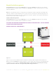
Mounting Hardware The SimpliPhi Power Mounting Brackets (sold separately) are designed to secure one PHI2.6™ Smart-Tech Battery to a load bearing surface. SimpliPhi Power Smart-Tech Batteries can be mounted in practically any orientation (Terminals Up, Down, On Side). The brackets can be mounted directly to a wall or can be arranged on strut channels for ease of positioning. A qualified installer should be familiar with accomplishing this with the appropriate load bearing requirements.
Figure 1.5 PHI2.6™ KWH 24V and 48V Battery Modules with Integrated Battery Management (BMS) SimpliPhi Power, Inc. | 420 Bryant Circle | Ojai, CA 93023, USA | +1 (805) 640-6700 | info@simpliphipower.com | SimpliPhiPower.
KEY POINTS 1. Each PHI2.6™ Smart-Tech Battery contains circuitry that protects the Lithium Ferrous Phosphate cells from overcharge, over-discharge, excessive charge and load amperage. If the values specified are exceeded, the Smart-Tech Batteries will enter a protective shut down state. In some cases this will result in the need to re-initialize an inverter charger or other pieces of equipment in the installation.
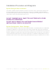
Connecting SimpliPhi Power PHI2.6™ Smart-Tech Batteries: Terminal Specs and Hardware CAUTION: DO NOT ATTEMPT TO LOOSEN THE LARGE BRASS NUT AT THE BASE OF THE TERMINALS. PHI2.6™ Smart-Tech Battery Connection Terminals The PHI2.6™ Smart-Tech Batteries are equipped with two 3/8’’ threaded studs with a lock washer and nut. The right hand stud resides in a red colored high temperature molded insert. This connection is for the positive lead. The left hand stud resides in a black colored high temperature insert.
Connecting Cable Leads to the PHI2.6™ Smart-Tech Batteries: NOTICE: SPARK MAY BE PRESENT WHEN CONNECTING WIRES TO PHI2.6™ TERMINALS A brief small spark is often present when connecting the second of two leads to a battery. Example: If the Positive has been connected, a small spark will likely be present when connecting the Negative lead. This is a normal occurrence. Complete all connections in a clean, ventilated, well lit area.
Most, if not all, inverters have related features. These features are often referred to as “Load Disconnect”, “Load Shedding” or similar. These features are there to protect the battery bank from excessive discharge. In instances of low battery voltage, when there is no incoming energy to recharge the battery bank, the inverter will disconnect the load and remain in standby until the battery bank is recharged.
Charge Controller Integration Per Manufacturers Recommendations 24-Volt System PRODUCT: PHI2.
Charge Controller Integration Per Manufacturers Recommendations 48-Volt System PRODUCT: PHI2.
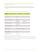
PHI Lithium Ferrous Phosphate (LFP) BMS Features and Specifications Model Numbers: PHI2.6™ 24V, PHI2.6™ 48V Feature Overview: BMS and 80 Amp Breaker • Over Charge Voltage Protection • Over Discharge Protection • Over Current Protection for Discharge Via Thermal Control • Short Circuit Protection • Cell Balancing • ON/OFF Switch Cell Pack Configuration • 2621Wh, 24V 102.4 Amp Hours • 2621Wh, 48V 51.2 Amp Hours Cell Voltage Parameters Max Charge Voltage 3.65V per Cell • 28.
All SimpliPhi Power products are designed to work exclusively in parallel. Never connect in series to achive higher voltages. PHI2.6™ Smart-Tech Battery Units Safety Attributes and Certifications/Green Characteristics SAFETY ATTRIBUTES AND CERTIFICATIONS Intrinsically Safe Operation and Installation The PHI Lithium Ferrous Phosphate (LFP) battery cell component is made with an intrinsically safe cathode material (iron phosphate).
Green Characteristics, Environmental and Ecological considerations Materials The primary materials (lithium, iron, phosphate) that make up PHI2.6™ Smart-Tech Batteries are environmentally benign and pose very few polluting or environmentally degrading by-products in the harvesting and refinement processes. This is especially true when compared to those of lead acid, NiCad, and NiMH batteries. By Products There are no toxic by-products associated with the assembly or use of PHI2.
Summary The Lithium Ferrous Phosphate (LFP) cells utilized throughout the entire PHI and LibertyPak product lines are classified as non-hazardous by OSHA and WHMIS. They are non-toxic, unlike NiMH, NiCad or Lead Acid types of batteries (including AGM). The PHI2.6™ Smart-Tech Batteries contain the least amount of toxic metals, and are the most eco friendly of all common battery types. Lithium easily combines into harmless compounds when disposed of. The PHI2.
Appendix MATERIAL SAFETY DATA SHEET SECTION 1 – PRODUCT IDENTIFICATION Product Name: Electronically Managed Energy Storage Device (Battery) Models: PHI2.6™, PHI3.4™ Product Use: Electric Power Supply - Harmony Code #8504.40.9540, Foreign Trade Schedule B Manufacturer: SimpliPhi Power, Inc., Ojai Ca. U.S.A. 805 640 6700 SECTION 2 - COMPOSITION AND INGREDIENT INFORMATION Under normal use, this battery dPHI not expose the user to hazardous ingredients. USA: This battery is an article pursuant to 29 CFR 1910.
Primary Route(s) of Exposure: Risk of exposure will only occur if the battery or cell is mechanically, thermally or electrically abused and the enclosure is compromised. If this occurs, exposure to electrolyte solutions contained within the battery or cell may occur by inhalation, eye contact, skin contact and ingestion. POTENTIAL HEALTH EFFECTS Inhalation: Inhalation of material from a sealed battery is not an expected route of exposure.
SECTION 6 – ACCIDENTAL RELEASE MEASURES The material contained within the batteries or cells is only expelled under abusive conditions. Use a shovel and cover battery with sand or vermiculite, place in an approved container and dispose in accordance with section 13. SECTION 7 – HANDLING AND STORAGE Handling: Do not expose battery or cell to extreme temperatures or fire. Do not disassemble, crush or puncture battery. Storage: Insulate positive and negative terminals to avoid short circuit.
SECTION 10 – STABILITY AND REACTIVITY Stability Conditions to Avoid Materials to Avoid Hazardous Decomposition Products Possibility of Hazardous Reactions Stable Avoid exposing battery to high temperatures over 452 degrees F.
SECTION 14 – TRANSPORT INFORMATION Hazardous Classifications: PHI Smart-Tech Batteries, PHI2.6™ and PHI3.4™ are categorized in the following manner and should be packaged, labeled, documented and declared accordingly: UN3481, Lithium ion batteries contained in equipment, 9, II.
Power. On Your Terms. SimpliPhi Power, Inc. | 420 Bryant Circle | Ojai, CA 93023, USA | +1 (805) 640-6700 | info@simpliphipower.com | SimpliPhiPower.