Power. On Your Terms. SimpliPhi AccESS Type 1.0 and 2.0 INSTALLATION MANUAL INSTALLATION MANUAL Optimized Energy Storage & Management for Residential & Commercial Applications Utilizing Efficient, Safe, Non-Toxic, Energy Dense Lithium Ferrous Phosphate (LFP) Chemistry © SIMPLIPHI POWER, INC.
SimpliPhi Your Energy Security and Independence and gain control of your own power. SimpliPhi Power helps you manage your power as a personal resource. Anytime. Anywhere. SimpliPhi energy storage optimizes integration of any power generation source – solar, wind, generator – on or off grid and protects your home and mission-critical business functions from power outages and intermittency.
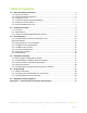
Table of Contents 1.0 – Important Safety Information ......................................................................................... 4 1.1 – Safety Instructions ......................................................................................................... 4 1.2 – Safety & Protective Features ......................................................................................... 5 1.3 – Limitations of Use .................................................................................
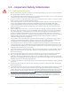
1.0 – Important Safety Information 1.1 – Safety Instructions 1. 2. 3. 4. 5. 6. 7. 8. 9. 10. 11. 12. 13. 14. Before using the unit, read all instructions and cautionary markings on the unit, the PHI 3.8 Batteries, and all appropriate sections of this manual. PHI 3.8 Batteries must be fully charged before commissioning the AccESS unit (i.e. before turning on connected loads). Failure to do so will void the Warranty.
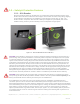
1.2 – Safety & Protective Features 1.2.1 – 80A Breaker All PHI 3.8 Batteries within the AccESS unit are outfitted with an 80A hydraulic/magnetic circuit breaker which will show a white base when tripped. This breaker increases safety during shipping and installations and allows the PHI 3.8 Battery to effectively be turned “OFF” or “ON.
PHI 3.8 Batteries do not vent any harmful gasses, and do not require special ventilation or cooling. PHI 3.8 Batteries are not capable of thermal runaway. As with any battery, if the cells are severely damaged due to physical abuse incurred outside of warranted specifications, it can cause electrolyte leakage and other failures. The electrolyte can be ignited by an open flame. However, unlike other lithium ion batteries (e.g. LCO, NCM, and NCA), the PHI 3.
1.3 – Limitations of Use The Conext XW Pro or XW+ Inverter/Charger built into the SimpliPhi Power AccESS is not intended for use in connection with life support systems or other medical equipment or devices. 1.4 – Inverter/Charger Programming Settings The Schneider Electric Conext XW Pro Inverter/Charger and XW+ Inverter/Charger has a firmware limitation that creates a potential issue with Lithium-Ion batteries: the Low Battery Cut-Out Voltage (LBCO) setting is limited to 48V maximum.
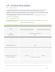
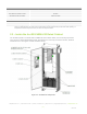
2.0 – Product Description 2.1 – Overview The SimpliPhi AccESS offers industry leading renewable energy storage technology to provide energy security and power resiliency into a pre-assembled, pre-programmed system that is suitable for installation inside and outside. The AccESS serves all of the common residential scale renewable energy applications: Off-Grid, Grid-Tied with Battery Back Up, Self Consumption – with Zero Export, Time Of Use (TOU) arbitrage and Peak Load Shaving for utility charge reduction.
Solar Charge Controller (select models) Schneider Electric Conext MPPT 80 600 Max Output Power 4.
The heart of the AccESS is the SimpliPhi Power PHI 3.8 kWh 48V 60A power storage modules. The power storage is modular and expandable. The base level energy storage is 11.4 kWh at 100 percent state of charge. This is provided by three PHI 3.8 kWh 48V 60A modules – combined in parallel. Energy storage within the AccESS enclosure can be expanded to 15.2 kWh with the addition of a fourth PHI 3.8 kWh 48V 60A battery module.
Conext ComBox easily connects with Conext Insight to enable you to remotely monitor a portfolio of sites from any internet connected device like a laptop or a tablet. • Conext Automatic Generator Start The ConextTM Automatic Generator Start (AGS) can automatically activate or stop a generator in response to changing power requirements.
3.0 – Pre-Installation The information within this section covers pre-installation procedures & considerations, namely, PHI 3.8 battery performance parameters to be aware of during the design process, guidance on system sizing, as well as installation site requirements and pad mounting. 3.1 – PHI 3.8 Battery Performance Parameters and Sizing Calculations The PHI 3.8 Batteries within the AccESS (both AccESS 1.0 and AccESS 2.
3.3 – Installation Tools and Materials • • • • • Digital Multi Meter AC/DC Clamp On Current Meter Wire Stripper Impact Driver Masonry Bolts 3.4 – Installation Site Location The AccESS may be installed indoors, such as a garage, or outdoors mounted onto a concrete pad. The cabinet is rated for NEMA-3R use. Please see Figure 3.0 below for physical AccESS dimensions, as this may impact the site location. Figure 3.0 – AccESS Unit Dimensions SimpliPhi Power, Inc.
3.5 – Clearance Requirements The AccESS should be installed with 3 inch (7.62 cm) clearance to the sides and 3 feet (0.91 m) clearance to the front to allow for the cabinet door to be opened during installation. Please see Figure 4.0 for details. All installations should comply with local code requirements and/or the local AHJ, which may exceed the requirements shown. Figure 4.0 – AccESS Unit Clearances SimpliPhi Power, Inc.
3.6 – Knock Out Locations Three 1.375-inch OD knockouts and one 2-inch OD knockout are located on both sides of the AccESS cabinet. They can be used for AC or DC inputs. Not all knockouts must be used. Figure 5.0 – AccESS Cabinet Knock-Outs (sides) 3.7 – Pad Mounting 3.7.1 – Pad Requirements The AccESS must be installed and secured on level concrete. For a pre-cast concrete pad, a 4” minimum thickness is required. The pad should be 3” wider than the AccESS on all sides (34” x 22” x 4”).
Figure 6.0 – AccESS Unit Knockouts (Bottom) SimpliPhi Power, Inc. | 3100 Camino Del Sol | Oxnard, CA 93030, USA | (805) 640-6700 | info@simpliphipower.com | SimpliPhiPower.
4.0 – Installation & Wiring This section covers how to install the PHI 3.8 Batteries within the AccESS unit, torque values, communications and network preparation and how to wire the AccESS unit. It also provides guidance on how to install optional AccESS unit components/accessories. 4.1 – Basic System Configuration Concepts Safe and reliable installation requires trained and certified technicians. The following discussion is a basic primer.
4.5 – Wiring the AccESS 4.5.1 – Wiring Diagrams Please reference the below listed DC coupling and AC coupling diagrams, where applicable. DC Coupled System 11.4 kWh, 5.7 kW (3) PHI 3.8 BATTERIES SimpliPhi Power, Inc. | 3100 Camino Del Sol | Oxnard, CA 93030, USA | (805) 640-6700 | info@simpliphipower.com | SimpliPhiPower.
AC Coupled System 11.4 kWh, 5.7 kW (3) PHI 3.8 BATTERIES CAUTION: Confirm the coupled grid-tie inverter’s compatibility with Schneider’s Conext XW Pro or Conext XW+ prior to installation. 4.5.2 – Making AC Connections AC Landing Points – Terminal Blocks The SimpliPhi Access is equipped with multiple knockouts on either side of the AccESS for accessibility to the AC connections. All AC connections are at 240 V.
Figure 7.0 - AC Power Input/Output Wiring Connection Points Generator AC Wiring For connecting a generator with the optional AGS from Schneider Electric, please refer to Schneider Electric’s AGS Installation Manual. CAUTION: On the Conext Mini PDP, an additional circuit breaker will need to be installed. The Generator will connect through this circuit breaker and to the XW Pro or XW+ 6848 inverter.
Figure 8.0 – Optional Generator Installation/Connection Diagram Inverter Charger Grounding The Conext XW Pro or XW+ is provided with ground terminals that must be reliably connected to ground (protective earth) by appropriately sized equipment grounding conductors. System grounding for the AC and DC systems must be done according to all applicable NEC and local installation codes.
4.5.3 – AC System Bonding Multiple AC Neutral-to-Ground Bonds Verify that only one neutral-to-ground bond exists in the system. Having more than one neutralto-ground bond in a system violates local electrical codes, may create a shock or fire hazard, and may cause some sensitive equipment to malfunction. Failure to follow these instructions can result in death or serious injury and will void the Warranty.
Figure 9.0 – PV Array Connection Points AccESS DC Grounding To connect the Conext XW Pro or XW+ to the DC grounding system, use the ground lug at the bottom of the Conext XW Pro or XW+ chassis. The terminal accepts wires from #14 AWG (1.63 mm) to #2 AWG (6.54 mm). System grounding for the DC system, which typically involves bonding (connecting) the PHI 3.8 Battery negative circuit to ground, is dependent on the system configuration.
Figure 10.0 – Inverter Power-Up Standby Display Step 3: Enable the Inverter Invert mode is enabled by default, and the Conext XW Pro or XW+ should begin inverting upon transitioning from standby mode. If invert mode is disabled, the inverter information panel will display "- - -" once out of standby mode, as shown below. If the Conext XW Pro or XW+ powers up in standby mode, press the STARTUP/ SHUTDOWN button momentarily to change the mode from standby to operating. Figure 11.
Figure 12.0 – Inverter Enabled Display To disable the inverter: On the inverter information panel, simultaneously press the STARTUP/ SHUTDOWN button and the Equalize button. The Conext XW Pro or XW+ is now disabled, and “diS” (disabled) is briefly displayed on the inverter information panel, followed by "- - -". Figure 13.0 – Inverter Disabled Display Monitor the invert (green kW) LED to confirm which mode the inverter is in: • kW LED OFF – Invert mode is disabled.
• kW LED ON – The inverter/charger is on. The inverter is operating and is able to provide power to the AC loads. This is the default mode on initial power-up once the unit is taken out of standby mode. If the inverter is not operating or the inverter LED (kW) does not turn on, check all connections. Check the inverter’s DC voltage and polarity on the positive (+) and negative (–) terminals. Check the Fault LED. If the fault LED is on, check for a fault code on the information panel.
Figure 15.0 – Inverter Charge Rate Display This completes the functional test. The internal set points have been pre-programmed for the PHI 3.8 Battery bank. 4.6 – AccESS Optional Components/Accessories Installation 4.6.1 – DC Coupled PV – 4.8 kW The AccESS may be DC Coupled with a PV system up to 4.8 kW DC. Please refer to Schneider Electric’s MPPT 80 600 installation manual and wiring diagrams for further information. 4.6.
5.0 – Programming 5.1 – Depth of Discharge The AccESS comes pre-programmed for 80% depth of discharge (DoD), assuming the AccESS is connected to an AC power source such as the grid or a generator. This qualifies for the 10-year / 10,000 cycle Warranty on the PHI 3.8 Batteries. To change the DoD to the 5,000 cycle Warranty or 3,500 cycle Warranty, modify the voltages in the Basic Settings and Advanced Settings per the Programming section. Refer to the PHI 3.8 Battery Warranty.
and thus optimizing cycle-life. Updated firmware for an increased programmable LBCO range may not be available in the Conext XW+. Table 3.0 – Programming Settings for SimpliPhi PHI 3.8 kWh 48V Battery w/Schneider Electric Inverter XW Pro or XW+ 6848 INVERTER – XW Pro or XW+ 6848 10K Cycles Warranty 5K Cycles Warranty 3.
Note: Instead of the Lithium Ion sub-menu, the Custom battery menu may be used instead. In this case, use the following settings: Table 4.0 – Programming Settings for SimpliPhi PHI 3.8 kWh 48V Battery w/Schneider Electric Inverter XW Pro or XW+ 6848 INVERTER – XW Pro or XW+ 6848 10K Cycles Warranty 5K Cycles Warranty 3.
Inverter Programming Settings for an AC Coupled System In an AC Coupled system, the only recommended system setup is a Grid-Tie with Battery Backup application. During normal system operation, this setup allows fo the coupled grid-tie inverter(s) to power the home’s loads and sell excess energy to the grid, while the batteries typically remain fully charged.
5.3.2 – MPPT Programming Settings Table 4.0 – Programming Settings for SimpliPhi PHI 3.8 kWh 48V Battery w/Schneider Electric Conext MPPT 80 600 XW MPPT80 10K Cycles Warranty 5K Cycles Warranty 3.
Set the Load Shave Start and Load Shave Stop parameters to the time frame during which utility rates are high. Set Load Shave Amps to 0A in order to draw no energy from the grid during the Load Shave time period. DC Coupled Scenario C: Grid-Tie with Battery Backup Both Sell and Grid Support must be enabled in order to export energy to the grid. Consult with the connected utility company before enabling Sell. Enable Grid Support in the inverter’s Setup menu.
5.3.4 – Auto Generator Start (AGS) Table 6.0 – Programming Settings for SimpliPhi PHI 3.8 kWh 48V Battery w/Schneider Auto Generator Start AGS 10K Cycles Warranty 5K Cycles Warranty 3.5K Cycles Warranty Advanced Settings > CFG Trigger 80% DoD 90% DoD 100% DoD Start DCV 30 sec Load Strt Load Stop Load 50.5V 49.8V 48V Enabled for the AccESS 1.0 Disabled (unnecessary) for 4 or more PHI 3.8’s 20A for the AccESS 1.0 18A for the AccESS 1.0 5.3.4 – PHI 3.
6.0 – SimpliPhi Technical Support For technical support related to your AccESS, please contact us as follows: 805.640.6700 techsupport@simpliphipower.com Appendix A – Schneider Electric Product Specifications A.
DC Current at Rated Continuous Power (Inverter Mode) 180 A Continuous Charge Rate at L-L voltage (Charger Mode) 140 A Power Factor Corrected Charging PF (0.98) Typical Transfer Time 8 ms A.2 – Schneider Electric Conext XW+ Grid Tie Specifications Function 120 V/240 V 120 V Response Time Anti-islanding reconnect 254.4 V (± 3 V) 127.2 V (± 3 V) 300 s (+1/–0 s) Over frequency disconnect 60.5 Hz (± 0.05 Hz) 60.5 Hz (± 0.05 Hz) 60 ms (± 20 ms) Under frequency disconnect 59.3 Hz (± 0.
A.3 – Schneider Electric Conext XW+ Series Inverter/Charger Overload Capability Loads connected to the inverter are seldom constant, and large loads are often operated for short periods. To accommodate larger loads, the Conext XW+ can temporarily exceed its continuous output power rating. The graphs below illustrate approximate operation time versus load.
A.4 – Schneider Electric Conext XW+ 6848 NA AC Overload Capability Figure 17.0 - Conext WX+ Operating Time vs 120VAC Load Graph A.5 – Schneider Electric Conext XW+ Output Power Versus Ambient Temperature When the internal temperature of the Conext XW+ exceeds a preset limit, it begins to limit output power automatically to stop maximum internal temperatures from being exceeded. Figure 18.0 - Conext WX+ Operating Temperature vs Load Graph SimpliPhi Power, Inc.
A.6 – Schneider Electric Conext XW+ Inverting Efficiency (Typical) Figure 19.0 - Conext WX+ Efficiency vs Load Graph A.7 – Schneider Electric Conext XW+ Charging Efficiency (Typical) Figure 20.0 - Conext WX+ Charge Efficiency vs Current Graph SimpliPhi Power, Inc. | 3100 Camino Del Sol | Oxnard, CA 93030, USA | (805) 640-6700 | info@simpliphipower.com | SimpliPhiPower.
A.8 – Schneider Electric Conext XW+ Charging Power Factor Figure 21.0 - Conext WX+ Charging Power Factor vs Current Graph SimpliPhi Power, Inc. | 3100 Camino Del Sol | Oxnard, CA 93030, USA | (805) 640-6700 | info@simpliphipower.com | SimpliPhiPower.