Power. On Your Terms. SimpliPhi AccESS with Sol-Ark 12K UL 9540 Certified for Residential Applications INSTALLATION MANUAL INSTALLATION MANUAL Optimized Energy Storage & Management for Residential Applications Requiring Units in 20kWh Increments. Utilizing Efficient, Safe, Non-Toxic, Energy Dense Lithium Ferrous Phosphate (LFP) Chemistry. © SIMPLIPHI POWER, INC.
SimpliPhi Your Energy Security and Independence and gain control of your own power. SimpliPhi Power helps you manage your power as a personal resource. Anytime. Anywhere. SimpliPhi energy storage optimizes integration of any power generation source – solar, wind, generator – on or off grid and protects your home and mission-critical business functions from power outages and intermittency.
Table of Contents 1.0 – Important Safety Information..................................................................................................................................... 4 1.1 – Safety Instructions ........................................................................................................................................................... 4 1.2 – Safety & Protective Features .........................................................................................................
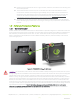
1.0 – Important Safety Information THE ACCESS UNIT AND PHI BATTERIES CONTAINED WITHIN THE UNIT MUST BE INSTALLED ACCORDING TO THE PROCEDURES OUTLINED IN THIS INSTALLATION MANUAL AND THE PHI BATTERY INSTALLATION MANUAL. ALL ACCESS UNIT OPERATION MUST BE IN ACCORDANCE WITH THE SETTINGS AND CONFIGURATION OUTLINED IN THIS MANUAL. FAILURE TO ADHERE TO EITHER THE ACCESS INSTALLATION MANUAL OR THE PHI BATTERY INSTALLATION MANUAL WILL VOID YOUR WARRANTY.
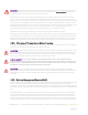
13. Remove personal metal items such as rings, bracelets, necklaces, and watches when working with electrical equipment. 14. The AccESS unit does not have any user-serviceable parts. Do not disassemble the inverter except where noted for connecting wiring and cabling. See your Warranty for instructions on obtaining service. Attempting to service the components inside the AccESS unit yourself may result in a risk of electrical shock or fire and void the Warranty.
CAUTION: Verify polarity at all connections with a standard voltmeter before 1) energizing the system and 2) turning the PHI 3.8 circuit breaker’s “ON/OFF” switch to the “ON” position. Reverse polarity at the battery terminals will void the Warranty and destroy the PHI batteries. PHI batteries pose some risk of shock or sparking during the installation and initial wiring and connection process. This is consistent with all other battery-based storage formats.
common amongst most inverter/chargers and should be anticipated if the PHI batteries go into a state of selfprotection and shut down the flow of electricity. CAUTION: While the BMS and internal circuit breaker protect the PHI battery from extreme electrical scenarios, neither will prevent the PHI battery from operating outside the recommended operating parameters.
2.0 – Product Description 2.1 – Overview The SimpliPhi Sol-Ark AccESS offers industry leading renewable energy storage technology to provide energy security and power resiliency in a pre-assembled, pre-programmed system that is suitable for installation inside and outside.
Output Frequency (selectable) 1 Bi-Directional Generator Port (63A double-pole); can be used for Smart Loads output 60 Hz or 50 Hz (50 Hz available upon request) Output Voltage L-N: 120VAC; L-L: 240VAC │ L-L: 208VAC (2/3 phases) │ 230VAC Off-Grid Output Power 9 kW Continuous On-Grid Output Power 9 kW Continuous Solar PV Continuous Power Delivered to Battery & AC Output 12 kW | To Grid: 9kW per Sol-Ark 12K MAX Continuous Batttery Power Max Battery Charging Current 185 ADC CEC Efficiency 96.
2.4–Inside the AccESS NEMA 3R Rated Cabinet The AccESS system is enclosed within a NEMA-3R rated cabinet. Within, the internal layout provides easy access to clearly labeled wiring points and includes the necessary overcurrent devices, breakers and disconnects. The heart of the AccESS is the SimpliPhi Power PHI 3.8 kWh 51.2Vnom energy storage modules. Additional storage capacity can be achieved by adding another BOSS.6 in parallel, side by side, with 4 or 5 of the PHI 3.8 kWh 51.
3.0 – Pre-Installation The information within this section covers pre-installation procedures & considerations, namely, PHI 3.8 battery performance parameters to be aware of during the design process, guidance on system sizing, as well as installation site requirements and pad mounting. 3.1 – PHI 3.8 Battery Performance Parameters and Sizing Calculations The PHI 3.8 batteries within the Sol-Ark AccESS are designed to operate at a continuous discharge rate of 11.
MISE EN GARDE: Ne pas associer les Batteries PHI avec d’autres marques et/ ou autres produits chimiques. Ne pas mélanger les Batteries PHI provenant de différentes installations, différents clients ou différents sites de travail. L’un ou l’autre de ces mélanges Annulera la Garantie. 3.3 – Installation Tools and Materials • • • • • Digital Multi Meter AC/DC Clamp-On Current Meter Wire Stripper Impact Driver Masonry Bolts 3.
Rain hood(s) optional Figure 3.0 – AccESS Unit Dimensions 3.5 – Clearance Requirements The AccESS should be installed with 3-inch (7.62 cm) clearance to the sides and 3 feet (0.91 m) clearance to the front to allow for the cabinet door to be opened during installation. Please see Figure 4.0 for details. All installations should comply with local code requirements and/or the local AHJ, which may exceed the requirements shown. SimpliPhi Power, Inc.
Figure 4.0 – AccESS Unit Clearances SimpliPhi Power, Inc. | 3100 Camino Del Sol | Oxnard, CA 93030, USA | (805) 640-6700 | info@simpliphipower.com | SimpliPhiPower.
3.6 – Knock Out Locations Three 1.375-inch OD knockouts and one 2-inch OD knockout are located on both sides of the AccESS cabinet. They can be used for AC or DC inputs. Not all knockouts must be used. Figure 5.0 – AccESS Cabinet Knockouts (sides) 3.7 – Pad Mounting 3.7.1 – Pad Requirements The AccESS must be installed and secured on level concrete. For a pre-cast concrete pad, a 4” minimum thickness is required. The pad should be 3” wider than the AccESS on all sides (34” x 22” x 4”).
Figure 6.0 – AccESS Unit Knockouts (Bottom) SimpliPhi Power, Inc. | 3100 Camino Del Sol | Oxnard, CA 93030, USA | (805) 640-6700 | info@simpliphipower.com | SimpliPhiPower.
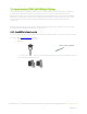
3.8 – Wire Run Lengths Two limiter sensors are included with the AccESS Sol-Ark. The limiter sensor wires are 10 feet long, and are extendable up to 50 feet using equipment from Sol-Ark (contact Sol-Ark directly at 972-575-8875; sales@solark.com). Consider this distance when deciding the Sol-Ark AccESS unit’s location relative to the home’s main breaker panel. 3.
4.0 – Installation & Wiring This section covers how to install the PHI 3.8 batteries within the AccESS unit, torque values, communications and network preparation and how to wire the AccESS unit. It also provides guidance on how to install optional AccESS unit components/accessories. 4.1 – Basic System Configuration Concepts Safe and reliable installation requires trained and certified technicians. The following discussion is a basic primer.
Figure 11.0b –Five PHI Battery Orientation Figure 11.0 a– Four PHI Battery Orientation 4. Attach interconnecting busbars onto the batteries’ terminals. Each positive busbar parallels one set of two or three batteries (positive to positive to positive), and each negative busbar parallels one set of two or three batteries (negative to negative to negative). 2 battery interconnecting busbars utilize a 31", 2 AWG cable. 3 battery inconnecting busbars utilize a 25", 2/0 cable. 5.
CAUTION: PHI 3.8 Batteries must be fully charged before commissioning the AccESS unit (i.e. before connecting loads for the first time). Failure to do so will void the Warranty. CAUTION: SimpliPhi does not require that the PHI 3.8 batteries within the AccESS be grounded. If a DC system ground is required, ensure that the system bonding is done in one location only, and that all conductors and connections comply with all applicable NEC and local installation codes. 4.
SimpliPhi Power, Inc. | 3100 Camino Del Sol | Oxnard, CA 93030, USA | (805) 640-6700 | info@simpliphipower.com | SimpliPhiPower.
4.5 – Communications and Network Preparation The AccESS System includes system-level monitoring and programming via PowerView ES Monitor and Programming software. For online guidance regarding the Sol-Ark’s WiFi setup, watch this video: https://www.youtube.com/watch?v=0H0OZfZz_kQ&feature=youtu.be Step-by-step WiFi setup instructions with screenshots and troubleshooting tips are included on pages 19 – 22 of the Sol-Ark-12K Manual. These excerpts also appear in Appendix A of this Manual.
4.5 – Wiring the AccESS 4.5.1 – Wiring Diagrams Please reference the below listed DC coupling and AC coupling diagrams, where applicable. DC Coupled System PV Array Connection To Batteries’ 5-Point Terminal Busbar (NEG) To Batteries’ 5-Point Terminal Busbar (POS) Figure 12.0 – DC Coupled AccESS Sol-Ark Wiring Diagram SimpliPhi Power, Inc. | 3100 Camino Del Sol | Oxnard, CA 93030, USA | (805) 640-6700 | info@simpliphipower.com | SimpliPhiPower.
AC Coupled System AC Coupled PV Array Connection To Batteries’ 5-Point Terminal Busbar (NEG) do not connect BTS To Batteries’ 5-Point Terminal Busbar (POS) no CAN Bus or RS485 connection Figure 13.0 – AC Coupled AccESS Sol-Ark Wiring Diagram SimpliPhi Power, Inc. | 3100 Camino Del Sol | Oxnard, CA 93030, USA | (805) 640-6700 | info@simpliphipower.com | SimpliPhiPower.
4.5.2 – Making AC Connections AC Landing Points – Terminal Blocks The AccESS is equipped with multiple knockouts on either side of the unit for accessibility to the Sol-Ark’s AC connections. All AC connections are rated at 120/240 VAC. The bi-directional grid port can also support two out of three phases of a 208 VAC grid connection (the two phases being L1 and L2, 120° out of phase).
Generator AC Wiring Generators wired to the Sol-Ark Split-Phase systems must be rated at 240VAC. Generators wired to the SolArk Three-Phase systems must be rated at 208VAC. Installations outside North America that incorporate generators rated at 230VAC / 50Hz can be wired to the Sol-Ark, provided there is no Neutral wiring connection. Generators can either be wired to the Sol-Ark’s Generator Input Port or to the Sol-Ark’s Bi-directional Grid Port.
4.5.3 – AC System Bonding Multiple AC Neutral-to-Ground Bonds Verify that only one neutral-to-ground bond exists in the system. Having more than one neutral-to-ground bond in a system violates local electrical codes, may create a shock or fire hazard, and may cause some sensitive equipment to malfunction. The Sol-Ark’s neutral busbar accepts wire sizes up to 4 AWG. Failure to follow these instructions can result in death or serious injury and will void the Warranty.
Figure 16.0 - AccESS Cabinet Knockouts (Sides) 3. Strip 0.5” of insulation from the PV conductors, and insert into the appropriate charge controller port. Figure 17.0 - PV Array Connection Points (DC Coupled Systems) 4. Ground the solar PV array by panel frame grounding to any ground connection in the home using 12 AWG wire. Solar PV mounting structures typically bond frames together, so only one ground wire is needed. SimpliPhi Power, Inc.
AccESS Sol-Ark System Solar PV Array Sizing The Sol-Ark-12K’s built-in MPPT charge controller specifications are: • Quantity of built-in MPPT charge controllers per Sol-Ark-12K = 2 o Quantity of PV ports per MPPT charge controller = 2 o Total quantity of PV ports per Sol-Ark-12K = 4 • MPPT charge controller starting voltage = 175VDC • Maximum DC Voltage input per MPPT charge controller = 500VDC • MPPT charge controller voltage range = 150-425VDC • Maximum ISC current input per MPPT charge controll
o 3. Eleven modules in series at the KuPower 300W module’s VMP rating of 32.5V at STC also equates to 357.5V, well within the charge controller’s 150-425VDC maximum power point tracking range. The charge controller’s maximum short circuit current (ISC) input is 33ADC. Temperature also slightly affects the solar PV module’s current output: current increases as temperature increases.
4.5.5 – Limiter Sensor Wiring Connections The Sol-Ark AccESS installation may include limiter sensors. Limiter sensors are required in the following applications: • Limited to Home mode • Time of Use Selling mode • Systems that include both a generator and grid connection Install limiter sensors on incoming electrical service wires L1 and L2, at the top of the main house breaker panel (refer to Sol-Ark’s diagram within their manual).
4.5.6 – Basic Functional Test The following procedure should be followed once the installation is complete and before it is put into service. Step 1: Confirm All Connections After the AC and DC wiring has been installed and connected, check that all connections are correct and secure. Step 2: Apply Battery Power to the Inverter 1. Measure the voltage and check polarity at all battery connection points.
Step 5: Fully Charge the Battery Bank Prior to Powering on Loads A connection to an AC power source will result in the Sol-Ark automatically charging the batteries from that power source when the Sol-Ark is turned ON. If the system does not include any AC power source, and only solar PV as the batteries’ charging source, turn on the PV disconnect and wait until the PHI battery bank has had a chance to charge fully via solar power before turning on any loads.
Step 6: Verify the lockout Once you’ve disconnected all primary and secondary sources of energy, attempt to start the equipment to verify that the lockout has been successful. Before you try to start it, verify that nobody is in a position where they could be hurt. Assuming that the procedures have been successful, return all switches and other equipment back to their “off” positions so the machine won’t start unexpectedly when the energy sources are reconnected.
5.0 – Programming 5.1 – Depth of Discharge The AccESS Sol-Ark comes pre-programmed for a maximum 80% depth of discharge (DoD) on the PHI batteries. This qualifies the batteries for the 10-year / 10,000 cycle Warranty. To change the batteries’ DoD to the 5,000-cycle Warranty or 3,500-cycle Warranty, modify the State of Charge (SoC) percentages as outlined in this Operating Parameters section of this Manual.
Figure 20.0 – Sol-Ark System Setup Screen Table 2.0 – Sol-Ark AccESS Battery Settings System Setup > Battery Setup 80% DoD (10k cycle warranty) 90% DoD (5k cycle warranty) 100% DoD (3.5k cycle warranty) > Batt Tab Batt Capacity1 75 Ah per PHI 3.8 battery Max A Charge1,2 37.5 ADC per PHI 3.8 battery (20 ADC per battery for reduced stress)* *The Sol-Ark’s maximum PV charging output is limited to 185 ADC. Max A Discharge1 37.5 ADC per PHI 3.
Float V 54 V Absorption V6 56 V 56 V Equalization V7 30 days 2 hours > Discharge Tab 80% DoD (recommended) 90% DoD 100% DoD Shutdown 20% (50.2 V) 10% (49.5 V) 0% (48 V) Low Batt 30% (50.5 V) 20% (50.2 V) 10% (49.5 V) Restart 97% (52 V) 97% (52 V) 97% (52 V) Batt Resistance Resistance mOhms = 96 ÷ (4 × PHI 3.
7. While the PHI Battery does not require an Equalization charge, programming Equalization to the voltage, frequency and duration outlined in the table above ensures that the Sol-Ark’s internal SoC meter re-sets to 100% SoC every 30 days. 8. Smart Loads are no longer powered via solar and/or batteries when the batteries’ SoC level drops below this programmed Smart Load OFF Batt value. 9.
Grid Setup Settings The Sol-Ark’s Grid Setup menu includes many advanced features (refer to Section 5 of this Guide). Regardless of the features used, the PHI battery bank should never discharge more than its maximum continuous discharge rate. Furthermore, to maintain the PHI batteries’ Warranty at a 10,000-cycle level, also do not discharge the battery bank to a State of Charge (SoC) level less than 20%. These details are controlled in the Grid Setup menu’s Limiter tab. Figure 21.
5.3 – Configuring the Sol-Ark to a Specific Application The Sol-Ark is capable of many different modes of operation via configurable settings (more than one mode can be used simultaneously). This section of the Manual will outline the system programming and setup basics for common use cases. However, refer also to the Sol-Ark Manual for all installation requirements relevant to the application at hand. Table 4.
Protect Param leave as default values when UL 1741 & IEEE 1547 are enabled frequency values may change when a generator is wired to the Grid Input > FreqVolt tab refer to the Sol-Ark Manual for Puerto Rico or Kauai-specific settings AC Coupled In an AC Coupled system setup, the grid-tie inverter(s) output – string or micro-inverters – is wired to the SolArk’s Generator Input (63A double-pole breaker) and the For Micro inverter input box in the Smart Load tab of the Battery Setup menu must be checked: Fi
A properly sized PHI battery bank based on the maximum draw of the essential loads sub-panel has a minimum of 4 batteries, even in this Grid-Tied with Battery Backup application. Note also that during a grid failure, the essential loads’ maximum energy draw (kWh) is also limited by the battery bank’s capacity.
Backup section of this Guide for battery bank sizing when batteries power the essential loads sub-panel only. Refer to the Discharge Example in Section 3 of this Guide for battery bank sizing when the batteries power both the essential loads sub-panel and the main house breaker panel.
Off-Grid The Sol-Ark automatically operates in Off-Grid mode when it does not detect a grid connection. In an Off-Grid system setup, all the home’s loads are connected to the Sol-Ark’s Load Output (50A double-pole breaker). Do not use the Sol-Ark’s Grid Sell and Limited to Home modes in an off-grid system setup. Check the Limited power to load box in the Limiter tab of the Sol-Ark’s Grid Setup / Grid Param menu to allow for the batteries’ power to discharge to the connected loads.
In an AC Coupled system setup that includes a generator, using a transfer switch for a grid-or-generator connection to the Sol-Ark’s Grid Input also frees up the Sol-Ark Generator Input for connection to the AC Coupled solar PV array. If the system includes both a generator and a grid connection, limiter sensors are required.
6.0 – Battery Recycling Our recycling company recycle majority of our battery parts, cells and support business and retail customers alike by keeping them in full compliance with federal, state, municipal, EPA and DOT regulations governing the recycling of waste batteries and select electronics.
Appendix A: Sol-Ark WiFi Setup Sol-Ark-12K Manual Excerpt (pg. 19-22) iPhone: https://apps.apple.com/us/app/powerview-es/id1460941008 Android: https://esem.cc/login SimpliPhi Power, Inc. | 3100 Camino Del Sol | Oxnard, CA 93030, USA | (805) 640-6700 | info@simpliphipower.com | SimpliPhiPower.
SimpliPhi Power, Inc. | 3100 Camino Del Sol | Oxnard, CA 93030, USA | (805) 640-6700 | info@simpliphipower.com | SimpliPhiPower.
SimpliPhi Power, Inc. | 3100 Camino Del Sol | Oxnard, CA 93030, USA | (805) 640-6700 | info@simpliphipower.com | SimpliPhiPower.
SimpliPhi Power, Inc. | 3100 Camino Del Sol | Oxnard, CA 93030, USA | (805) 640-6700 | info@simpliphipower.com | SimpliPhiPower.
SimpliPhi Power, Inc. | 3100 Camino Del Sol | Oxnard, CA 93030, USA | (805) 640-6700 | info@simpliphipower.com | SimpliPhiPower.
Appendix B: Rapid Shutdown Compliance Sol-Ark Manual Excerpt SimpliPhi Power, Inc. | 3100 Camino Del Sol | Oxnard, CA 93030, USA | (805) 640-6700 | info@simpliphipower.com | SimpliPhiPower.
SimpliPhi Power, Inc. | 3100 Camino Del Sol | Oxnard, CA 93030, USA | (805) 640-6700 | info@simpliphipower.com | SimpliPhiPower.