
Specification

C-2013 © 2013 SIMPSON STRONG-TIE COMPANY INC. PRINTED 12/12
143
Plated Truss Connectors
THJM
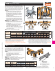
Multiple Truss Hip Jack Hanger
Plated Truss Connectors
Typical THJM Installation
The new THJM is a non-welded hanger designed to carry
radial-end jack framing and provide optimal efficiency for those
multi-plane, angled bay roofs over breakfast, study and library
alcoves. The unique patent pending design of the THJM accom-
modates 2x4 girder bottom chords and uses our Strong-Drive
®
SDS screws for easy installation with minimal fasteners.
FEATURES:
•TheTHJMhangersaredesignedforinstallationwith
SDS
1
⁄
4
"x3" screws that are included with the parts.
•TheTHJM2-4-SDS3isdesignedforfourincomingjack
trusses with the outer jacks being 22
1
⁄
2
° from the face
of the girder and the inner jacks being 45° from each
other and the outer jacks.
•TheTHJM2-5-SDS3isdesignedforfivejackscoming
into the hanger at 30° from the girder and each other.
•TabsontheseatsoftheTHJMassistintheplacement
of the jacks and also include obround holes for optional
slant nails (10dx1
1
⁄
2
") when increased uplift is required.
MATERIAL: 12 gauge FINISH: Galvanized
INSTALLATION:•Useallspecifiedfasteners.SeeGeneralNotes.
•EachcarriedjacktrussrequiresoneSDS
1
⁄
4
"x3" screw
installed into the bottom chord through the bottom of
the hanger seat.
•Forinstallationongirderswith2x6or2x8bottom
chords, install one additional SDS
1
⁄
4
"x3" screw in
the triangular hole on each vertical strap.
•Installtwo(2)10dx1
1
⁄
2
" slant nails in the obround holes
on each of the seat tabs to achieve the additional uplift
load noted in the footnote.
CODES: See page 13 for Code Reference Key Chart.
3"
3½"
Typ.
5"
1½"
1½"
THJM2-4-SDS3
(THJM2-5-SDS3 similar)
U.S. Patent Pending
DSC
Drag Strut Connector
1. Allowable loads have been increased 60% for wind or earthquake loading
with no further increase allowed; reduce where other loads govern.
2. Simpson Strong-Tie SDS screws minimum penetration is 2
3
⁄
4
", minimum
end distance is 2
1
⁄
2
" for DSC2 and 3
3
⁄
4
" for DSC5 and minimum edge
distance is
5
⁄
8
" for full load values.
3. Simpson Strong-Tie
®
Strong-Drive
®
SDS screws are permitted to be installed through metal
truss plates as approved by the Truss Designer, provided the requirements of ANSI/TPI 1-2007
Section 7.5.3.4 are met (pre-drilling required through the plate using a maximum of
5
⁄
32
" bit).
Typical DSC5R-SDS3
Installation
(DSC2 similar)
L/2
3"
3
3
⁄4"
TYP.
3"
L
DSC5R/L-SDS3
(DSC2 similar)
(Right hand DSC shown; specify
right or left hand when ordering)
U.S. Patent 6,655,096
Model
No.
L
(in.)
Fasteners
DF/SP Allowable Loads SPF/HF Allowable Loads
Code
Ref.
Compression
(160)
Tension
(160)
Compression
(160)
Tension
(160)
DSC2R/L-SDS3 16 20-SDS
1
⁄
4
"x3" 2590 3720 1865 2680
F12
DSC5R/L-SDS3 21 24-SDS
1
⁄
4
"x3" 4745 5925 3415 4265
The DSC drag-strut connector transfers the diaphragm shear
forces from the girder truss or beam to the shearwalls. The new
DSC5 has been designed to optimize fastener location, resulting
in a connector that outperforms the DSC4 with fewer fasteners. The
DSC2 is a smaller, lighter version that installs with fewer screws.
FEATURES
•TheDSC5requires40%fewerfastenersthanour
previous DSC4, and gets 12% higher loads
•Lefthandandrighthandversionsavailable
•DSCsinstallwiththeSimpsonStrong-Tie
®
SDS
1
⁄
4
"x3"
screws provided
MATERIAL: DSC2—7 gauge, DSC5—3 gauge
FINISH: DSC2—Galvanized; DSC5—Simpson Strong-Tie
®
gray paint
INSTALLATION:•Useallspecifiedfasteners;seeGeneralNotes.
•Strong-Drive
®
SDS screws are provided.
CODES: See page 13 for Code Reference Key Chart.
1. Tabulated loads are the total allowable loads of all carried members combined;
the load on any single carried member shall not exceed 25% of the total published
load for the THJM2-4 or 20% of the total published load for the THJM2-5.
2. Uplift loads have been increased for wind or earthquake loading with no
further increase allowed. Reduce where other loads govern.
3. A minimum 2-ply carrying member is required for the SDS
1
⁄
4
"x3" screws
(provided). For single 2x carrying members, use SDS
1
⁄
4
"x1
1
⁄
2
" screws (not supplied)
with corresponding loads.
4. A minimum 2-ply carrying member is required for the tabulated loads.
5. Truss chord cross-grain tension may limit allowable loads per ANSI/TPI 1-2007.
The optional triangle holes may be used for installation on 2x6 and larger carrying
members, for a total of 10 fasteners into the carrying member, to resist cross-grain
tension forces when no other mechanical reinforcement is available.
6. Tabs on the seats of the THJM hangers have obround holes for optional 10dx1
1
⁄
2
" slant
nails (2 per carried member) when additional uplift capacity is required. Total allowable
uplift with the optional 10dx1
1
⁄
2
" slant nailing is 970 lbs. (DF/SP/SPF/HF).
Model No.
Fasteners DF/SP Allowable Loads SPF/HF Allowable Loads
Code
Ref.
Carrying Member
3
Carried Members
(Total)
Total
Uplift
(160)
6
Total Download
Total
Uplift
(160)
6
Total Download
Floor
(100)
Snow
(115)
Roof
(125)
Wind
(160)
Floor
(100)
Snow
(115)
Roof
(125)
Wind
(160)
THJM2-4-SDS3
8-SDS
1
⁄
4
"x1
1
⁄
2
" 4-SDS
1
⁄
4
"x3" 535 2000 2300 2500 3030 535 1440 1655 1800 2180
I13
8-SDS
1
⁄
4
"x3" 4-SDS
1
⁄
4
"x3" 535 3270 3270 3270 3270 535 2355 2355 2355 2355
THJM2-5-SDS3
8-SDS
1
⁄
4
"x1
1
⁄
2
" 5-SDS
1
⁄
4
"x3" 620 2000 2300 2500 3030 445 1440 1665 1800 2180
8-SDS
1
⁄
4
"x3" 5-SDS
1
⁄
4
"x3" 620 3360 3765 3765 3765 620 2420 2710 2710 2710
THJM2-4-SDS3
Top View Installation
7"
45˚
45˚
22.5˚
22.5˚
Working
Point
45˚
THJM2-5-SDS3
Top View Installation
8
5
⁄
8
"
30˚
30˚
30˚
30˚
30˚30˚
3
⁄
4
" Typ.
Working
Point