
Product Brochure


16
Strong-Drive
®
SDWH TIMBER-HEX HDG Screw
© 2019 Simpson Strong-Tie Company Inc. F-F-SDWHHDG19
Round Piling
Pile Size
(in.)
Total Stringers —
Qty. and Size
(in.)
Stringer
Type
Total
Fasteners —
Qty. and Model
Notched
Pile ?
Minimum
Notched
Pile Depth
(in.)
Detail
No.
Allowable Connection Loads (lb.)
Uplift Lateral
Continuous Butt End Continuous Butt End
12 (1) 2 x 10 SP (4) SDWH27600G N —
RP2
2,020 1,445 1,010 2,020 1,540 1,010
12 (1) 2 x 10 SP (4) SDWH27600G Y 10
½
1,555 1,505 780 2,020 1,670 1,010
12 (2) 2 x 10 SP (4) SDWH27800G Y 9 2,045 1,655 1,025 1985 1,565 995
12 (3) 2 x 10 SP (4) SDWH27800G Y 7
½
2,390 1,680 1,195 2,310 2,030 1,155
12 (1) 4 x 10 DFL (4) SDWH27800G Y 8
½
1,605 1,095 805 1,825 1,560 915
12 (1) 1.75 x 9.5 LVL / LSL (4) SDWH27600G Y 10
¼
1,425 1,425 715 2,090 2,090 1,045
12 (2) 1.75 x 9.5 LVL / LSL (4) SDWH27800G Y 8
½
1,605 1,095 805 1,825 1,560 915
12 (1) 3.5 x 9.25 PSL PLUS (4) SDWH27800G Y 8
½
1,695 1,405 850 1,615 1,250 810
12 (1) 3.125 to 3.5 x 9.5 Glulam (4) SDWH27800G Y 8
½
1,985 1,880 995 1,445 1,445 725
12 (3) 1.75 x 9.5 LVL / LSL (4) SDWH27800G Y 6
¾
1,605 1,420 805 1,520 1,520 760
12 (1) 5.25 x 9.25 PSL PLUS (4) SDWH27800G Y 6
¾
1,605 1,420 805 1,520 1,520 760
12 (1) 5.25 x 9.5 Glulam (4) SDWH27800G Y 6
¾
1,420 1,400 710 2,215 1,845 1,110
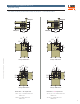
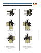
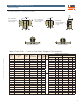
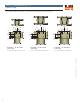
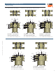
One-Sided, Single-, Double- or Triple-Ply Stringer — Continuous Condition (End Condition Similar)
2"
1"
1"
3
¼"
1½" 1½"
1"
C
L
1"
2"
1"
1"
3
¼"
1½" 1½"
1½"1½"
L
C
Detail RP1
8" Round Piles
Detail RP2
10" and 12" Round Piles
Section View
NotchedUnnotched
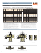
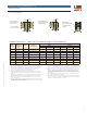
Table 5: Round Piles — Loads for One-Sided, Stringer-to-Pile Connection (cont.)
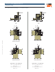
One-Sided Stringers
Notched, Lap
(Outer Ply Butt, Inner Ply Continuous similar)
Notched, Butt
1. Design of framing (stringers) and columns is by others.
2. Wooden piles and framing are Southern Pine (SP) or engineered wood
products with minimum specific gravity or equivalent specific gravity of 0.50.
3. Use the screw length cited in the tables and details.
4. Dimensions and allowable connection loads are based on notched piles that
must accommodate the stringers with adequate bearing and no gaps.
5. Notched piles shall not be notched such that more than 50% of the cross
section is removed.
6. Unnotched piles may be assigned notched pile loads if the unnotched pile
dimensions meet or exceed the maximum dimensions for the notched pile
and fastener placement is the same.
7. Tabulated values shall be multiplied by all applicable service adjustment
factors per the NDS. Allowable loads are shown with a load duration factor of
C
D
= 1.0. Loads may be increased for load duration per the building code up
to C
D
= 1.6. For service moisture content greater than 19%, use C
M
=0.70.
8. When the connection on an unnotched pile is simultaneously loaded in more
than one direction, the allowable load must be evaluated using the unity
equation: (Design uplift/Allowable uplift) + (Design lateral/Allowable lateral) +
(Design vertical/Allowable vertical) ≤ 1.0. If notched piles are used, the last
term is zero.
9. For stringer thickness at least 1.5" and less than 3", use the table values for
the conditions with a single 2x stringer.
10. Butt loads are based on all stringer members butted. For multi-ply stringers
where one stringer is continuous, use the tabulated loads in the “Continuous
and Lap” column. Refer to figures for details.