Pressure Washers and Accessories KING BRUTE (KB0001 - KB3030 ) Operators Manual and Parts Lists Simpson Pressure Washers LIT- KING Manual Page 1
INTRODUCTION Thank you for selecting a high pressure power washer from Simpson Pressure Washers. Your pressure washer has been manufactured using the most advanced components in the pressure industry. When operated properly, our equipment has been designed and manufactured to give you years of trouble free, reliable use, with a minimal amount of regular maintenance.
PRESSURE WASHER LIMITED WARRANTY 1. Simpson® Cleaning Systems, LLC warrants its products for a period of one year from the date of purchase, against defects in material and/or workmanship. The warranty covers parts and labor, but excludes transportation. 2. Normal wear and tear items such as valves, seals, etc., are warranted for the initial 30 days following purchase by the end-user. 3.
IMPORTANT SAFETY PRECAUTIONS IMPORTANT: Please read the following instructions before installing and operating this equipment. DANGER THIS EQUIPMENT CAN BE HAZARDOUS TO OPERATOR SAFETY AND ONLY AUTHORIZED PERSONNEL WHO HAVE READ AND UNDERSTAND THE INSTALLATION AND OPERATION MANUAL SHOULD BE PERMITTED TO OPERATE THIS EQUIPMENT. DO NOT LEAVE WAND UNATTENDED WHILE EQUIPMENT IS RUNNING.
14. Always cool down coil. DO NOT’S DO NOT - UNDER ANY CIRCUMSTANCES - POINT THE HIGH PRESSURE NOZZLE AT YOURSELF, OTHER PEOPLE, OR ANIMALS! 1. DO NOT use an undersized discharge nozzle. 2. DO NOT disconnect the pressure hoses or wand while the equipment is HOT, PRESSURIZED or RUNNING. 3. DO NOT operate this equipment without sufficient water supply to the pump. 4. DO NOT operate this equipment without proper ventilation or in a closed space. 5.
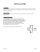
INSTALLATION 1. LOCATION Avoid operating units in small areas or near exhaust fans. Adequate oxygen is needed for combustion or dangerous carbon monoxide will result. Stationary units should be installed in accordance with local plumbing and heating codes. 2. FUEL SUPPLY Oil Fired Units: Fill fuel tank with clean kerosene, No. 1 home heating fuel, or diesel fuel (without anti-gel additives.) 3. VENTING THE UNITS If the unit is to be used in an enclosed area it must be vented out.
OPERATING THE MACHINE PRE-OPERATING INSTRUCTIONS 1. Connect the swivel end of the discharge hose to the cleaning gun. 2. Attach the hose to the machine outlet. 3. Check the fuel level in the fuel tank. Add fuel if required. It is best to keep fuel tank full during nonworking conditions. 4. Attach an ordinary garden hose to the pump/unit inlet. Turn on the water supply and let the water flow trough the unit. 5. Place the end of the soap line into your soap solution container.
SHUT DOWN INSTRUCTIONS 1. If the burner is on, set the switch to the OFF position 2. Run water through the pump until cool water flows from the cleaning gun. Failure to do this could result in increased coil scaling. 3. Turn the engine control switch to off. 4. Turn off the water supply. 5. If the machine will be exposed to freezing temperatures, see winterizing procedure. THINGS TO CHECK DAILY 1. Check oil level in pump. 2.
MAINTENANCE OF COMPONENTS PUMPS 1. Refer to pump section in this manual for your model of equipment. 2. Change pump oil after the first 25 hours of use. hours or 3 months, whichever comes first. Subsequent changes should be every 250 A. Engine must be off. Disconnect the battery. B. Remove drain plug on pump and drain oil. C. If the oil has water in it, it is important to flush out the pump with oil before refilling pump with the proper oil. 3.
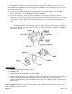
6. FUEL PUMP: To bleed air out of fuel pump, open air bleed valve on side of fuel pump. Turn machine and burner ON. When fuel looks clear (NOT FOAMING), close air bleeding valve. Air is out of fuel lines and fuel pump. A. To check fuel pressure, plumb a 200 PSI gauge into the port marked gauge. DO NOT USE BLEED VALVE PORT TO CHECK FUEL PUMP PRESSURE. B.
DE-SOOTING COIL Poor grades of fuel oil or inadequate combustion air will cause heavy soot build up on the outside surface of the heating coil. This will insulate the coil and restrict air flow through the coil, further aggravating the soot build up. To clean off soot, add Red Devil Soot Remover, using manufactures mixing instructions, or remove coil and clean thoroughly, or Call a Factory Authorized Simpson Dealer.
DIAGNOSIS AND MAINTENANCE PROBLEM Low Pressure Pulsation, pump runs extremely rough, pressure low. Water leakage from under the manifold Oil leak between crankcase and pumping section *Slight leakage. Oil leaking in area of crankshaft Excessive play in the end of the crankshaft.
Notes: Manual Page 13
PUM0015 17 16 10 14 11 12 15 28 13 27 24 20 2 9 25 4 7 6 3 72 23 30 32 31 27 4 2 74 27 69 28 40 28 36 73 22 8 33 5 1 18 19 21 1 3 71 35 41 42 67 44 34 37 38 70 57 Repair Kits 23 (3) 3 (6) 24 (3) 25 (3) 4 (6) Valve Kit # PPA1554 Qty 6 of each part included per kit 21 (3) 32 (3) 10 42 33 (3) 22 (3) Piston Kit # PPA1555 Qty 3 of each part included per kit 16 30 (3) 7 (3) Water Seal Kit #PPA 1556 Qty 3 of each part included per kit Pos Part # Description
PPA0015 Unloader 1 2 11 3 12 4 13 14 16 18 15 5 17 6 20 19 7 21 22 8 23 9 24 10 Repair Kits Repair Kits 11 12 (2) 13 14 15 16 18 19 Unloader Kit PPA1586 Pos CodeQty Pos Part # Description 1 2 3 4 5 6 7 8 9 10 11 12 13 14 15 16 17 18 19 20 21 22 23 24 PPA1560 PPA1561 PPA1562 PPA1563 PPA1564 PPA1565 PPA1567 PPA1568 PPA1569 PPA1570 PPA1572 PPA1573 PPA1574 PPA1575 PPA1576 PPA1577 PPA1578 PPA1579 PPA1580 PPA1581 PPA1582 PPA1583 PPA1584 PPA1585 PPA1586 PPA1587 Cap Screw Nut KnobUnloader Adjust
ALTERNATE PUMP PARTS LIST AND EXPLODED VIEW
BURNER COMPONENTS - MODEL MSR MSR BURNER MODEL, PART DESCRIPTION AND PART NUMBER WHEN ORDERING PARTS NO. 1 2 3 4 5 6A 6B 6C 7A 7B 7C 8 9A 9B 9C 10 11 12 DESCRIPTION BURNER HOUSING JUNCTION BOX ASM MOTOR 1/8 H.P.
AIR TUBE & GUN ASSEMBLY DETAILS MODEL MSR NOTE: BACKSIDE OF FLAMELOCK TO NOZZLE FACE. TO DETERMINE THE AIR TUBE LENGTH 5/16” NO. 17 DESCRIPTION PART NO. HEAD 0.85-0.75 #SC 100060 0.75-1.00 #1A 14157 1.00-1.35 #2A 14158 2.00-2.25 #4A 14160 18 AIR TUBE SEE NOTE 19 NOZZLE ADAPTER 21913-SER 20 RIGHT ELECTRODE ASSY. SEE NOTE 21 LEFT ELECTRODE ASSY. SEE NOTE 22 ELECTRODE SUPPORT ASSY. SEE NOTE 23 OIL PIPE ASSY.
ELECTRICAL SCHEMATIC (12VDC) Manual Page 16
GUNVALVE AND HOSE ASSEMBLY COMPONENT LOCATOR Manual Page 18
GUNVALVE AND HOSE ASSEMBLY COMPONENT LOCATOR PARTS LIST Ref. No. 1 2 3 4 5 6 7 8 9 10 11 12 Manual Qty. 1 1 1 1 2 1 1 1 1 1 1 1 Part No.
GC 590-40 GUNVALVE COMPONENT LOCATOR Manual Page 20
GC 590-40 GUNVALVE COMPONENT LOCATOR PARTS LIST Ref. No. Qty. Part No.
1111 E. Lake Francis Dr.