Installation manual Simrad 50-7 50 kHz Single beam transducer www.SIMRAD.
Simrad 50-7 Installation manual This document provides a general description of how to install the Simrad 50-7 Single beam transducer. The information must be regarded as general guidelines and recommendations only. The installation shipyard must design and manufacture installation hardware to fit the 50-7 transducer on each individual vessel.
Document history Document number: 305270 / ISBN-10: 82-8066-075-5 / ISBN-13: 978-82-8066-075-6 Rev.A August 2006 Original issue. Copyright ©2006 Simrad Horten AS Disclaimer The information contained in this document remains the sole property of Simrad Horten AS. No part of this document may be copied or reproduced in any form or by any means, and the information contained within it is not to be communicated to a third party, without the prior written consent of Simrad Horten AS.
Installation manual Table of contents INTRODUCTION ................................................................ 5 TRANSDUCER LOCATION .................................................. 6 Go deep.....................................................................................................................6 Vessel heave .............................................................................................................6 Noise from protruding objects on the hull.............................
Simrad 50-7 4 305270/A
Introduction INTRODUCTION The purpose of this manual is the provide the basic information required to install the 50-7 Single beam transducer. Note that although drawings are provided to explain the installation principles, the installation shipyard must provide the final drawings required to fit each individual vessel. Also, when applicable, the installation shipyard must have the drawings and installation approved by the proper authorities. Transducer order number: KSV-203665.
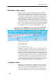
Simrad 50-7 TRANSDUCER LOCATION A single answer to the question where to locate the transducer cannot be given. It depends very much on the vessel’s construction. However, there are some important guide lines. Go deep The upper water layers of the sea contain a myriad of small air bubbles created by the breaking waves. In heavy seas the uppermost 5 to 10 metres may be air-filled, with the highest concentrations near the surface.
Transducer location Boundary water layer When the vessel forces its way through the sea, the friction between the hull and the water creates a boundary layer. The thickness of the boundary layer depends upon vessel speed and the roughness of the hull. Objects protruding from the hull, and dents in the hull, disturb the flow and increase the thickness of the boundary layer. The flow in this boundary layer may be laminar or turbulent. A laminar flow is a nicely ordered, parallel movement of the water.
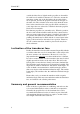
Simrad 50-7 outside the direct line of sight from the propeller are favourable. On small vessels with short distances it is advised to mount the transducer on that side of the keel where the propeller blades move upwards, because the propeller cavitation is strongest on the other side. The cavitation starts most easily when the water flows in the same direction as the propeller blade, and that is to some degree the case at that side of the keel where the propeller blades move downwards.
Transducer location A (CD017004Q) L B M General recommendation for transducer location: (A) = Transducer (B) = Inclination angle (L) = Hull length at water line (M) = Maximum 1/3 of the hull length at water line (L) (CD17004C) If the vessel hull has a bulbous bow, this may well be a good transducer location, but also here must be taken into consideration the flow pattern of the aerated water. Often the foremost part of the bulb is preferable.
Simrad 50-7 WAYS OF MOUNTING THE TRANSDUCER There are many different ways to mount the transducer. These are the recommended methods to mount a circular transducer.
Ways of mounting the transducer Transducer blister With a transducer with circular housing, one recommended installation method is by using a blister. The transducer blister must be designed and manufactured by the installation shipyard to fit the vessel’s size and hull shape. Mounting and clamping rings Circular transducers may be provided with mounting and clamping rings, or with drawings to allow for local production of these.
Simrad 50-7 Example: Large transducer The illustration below shows a typical transducer blister designed for a large transducer. Note that due to the physical size of the transducer, a U-shaped support bar (E) is used to support the transducer. The purpose of this support is to prevent the transducer from being pushed up into the blister in heavy seas.
Ways of mounting the transducer Example: Small transducer The illustration below shows a typical transducer blister designed for a small transducer. The same blister design principles as for a large transducer apply. E E A B (CD017010B) F G C D (A) = Streamlined blister (E) = Air outlet (B) = Mounting ring (F) = Forward (C) = Clamping ring (G) = Transducer cable (D) = Guide Note that the transducer cable must be provided with a cable loop inside the blister.
Simrad 50-7 Example: Medium sized transducer without clamping ring The illustration below shows a transducer blister designed for a medium sized transducers. The same blister design principles apply. Note that the transducer is mounted without a clamping ring, which makes it necessary to use a different mounting ring design.
Ways of mounting the transducer Common guidelines The best performance is obtained with a blister height of 40 cm or more. A streamlined shape and rounded edges reduce the flow noise. A vertical leading edge or front will guide the aerated water to the sides of the blister. The orientation of the blister should follow the water flow. The interior of the blister must be filled with sea water. Use drainage holes in the bottom and an air outlet on the top.
Simrad 50-7 Observe the horizontal and vertical distances (X and Y) between the keel and the transducer blister. On a medium sized vessel, the horizontal distance (X) should be approximately 1 meter. The vertical distance (Y) must in general be as small as possible. This is important to prevent the keel from shadowing the transducer beam in shallow waters.
Ways of mounting the transducer Box keel Vessels with a box keel may use this for transducer installation. The box keel is already the deepest part of the vessel. If the box keel is too narrow to accommodate the transducer, it can be widened, either symmetrically or to one side only. In the last case the installation could also be described as a blister merged into the keel.
Simrad 50-7 Example (CD17011A) The figure below illustrates a symmetrical box keel installation.
Ways of mounting the transducer Flush mounting in a steel tank Flush mounting is used on very large vessels with a hull so deep that no air bubbles are found below the hull, and on vessels operating in shallow harbours or waters, where a protruding blister can not be accepted. The standard procedure for flush mounting on a steel vessel is to weld a steel tank inside the hull, and mount the transducer into this tank.
Simrad 50-7 Example Transducer mounting in a steel tank is shown in the figure below.
Ways of mounting the transducer Acoustic window Vessels operating in arctic waters need special attention on transducer installation. Floating blocks of ice may damage even a flush mounted transducer face. For this situation Simrad offers arctic tanks in different sizes. Mounting and clamping rings Circular transducers may be provided with mounting and clamping rings, or with drawings to allow for local production of these.
Simrad 50-7 Example The transducer shown in the figure below is mounted inside the tank behind a strong acoustic window which could be made of polycarbonate. The tank is filled with oil.
Ways of mounting the transducer Inside the hull The transducer can also be mounted inside the hull. An installation of the transducer inside the hull, and sounding through the hull, requires a good acoustic contact between the transducer face and the hull. Build a tank around the transducer and fill it with a liquid. Oil used in hydraulic systems is a well suited liquid for this purpose. It contains no gas bubbles and is non-corrosive.
Simrad 50-7 Example The transducer shown in the figure below is mounted inside the hull. The tank is filled with oil.
Ways of mounting the transducer Drop keel The use of a drop keel with the purpose of stabilising the vessel is well known. A drop keel is also a superior platform for echo sounder transducers. Such instrument keels have been built, mainly on research vessels, often protruding as far as three meters below the hull. At that depth, the water is free of air bubbles up to very high sea states. The vessel is then able to perform reliable acoustic measurements in open sea a larger part of the year.
Simrad 50-7 Retractable transducer Hull units allowing the transducer to be lowered and hoisted are commonly used for horizontal looking sonars. When not in use, the transducer is retracted into a trunk. The retractable hull unit is more expensive than a blister, but on vessels with a hull where it is difficult or impossible to install a blister, it may still be worth while. The principles of a hull unit with a retractable transducer is shown below.
Cable glands CABLE GLANDS The transducer cable must pass through the hull using approved cable glands for the type of vessel in question. A steel cable gland is normally used on professional vessels with steel hulls. A bronze cable gland can be delivered as an option for vessels with wood or fibreglass hulls. Vessel not to be classified can as an option use a cable gland made of plastic.
Simrad 50-7 Cable gland for steel hulls This cable gland kit is designed for steel vessels. It must be welded to the hull plates. F ø35 A A ø65 B C D C E (CD17008A) (A) = Steel conduit (B) = Stuffing tube, DNV approved carbon steel st52.3 (C) = Washers, 24 x 8 x 2 mm (D) = Rubber gasket (E) = Packing nipple.
Cable glands Cable gland for wood or GRP hulls A bronze cable gland kit is available for wood and GRP vessels. F A E B C B C D B C (CD17008B) (A) = Packing nipple. Make sure that you do not damage the transducer cable by tightening the packing nipple too hard! (B) = Washers (C) = Rubber gaskets (D) = Hole diameter 28 mm (E) = Steel conduit (F) = Cable to the echo sounder (or a junction box) The cable gland kit includes all of the necessary parts needed to install the unit except screws.
Simrad 50-7 Cable glands for small hulls This cable glands made of plastic is designed for those smaller vessels that do not need to be classified. J A B A C D E F (CD17008C) G H I (A) = Packing nut (bronze). Ensure that you do not to damage the transducer cable by tightening the packing nut too hard! (B) = Rubber gasket (C) = Plastic disk (D) = Rubber gasket (E) = Stuffing tube (F) = Backing nut (bronze) (G) = Backing washer (plastic) (H) = O-ring 42.5 x 3.0 N (I) = O-ring 39.5 x 3.
Cable glands Cable splicing If you need to cut the transducer cable, you must splice it correctly. Note DO NOT solder the wires together with only electrical tape for insulation, as this will result in electrical noise and reduced operational performance. To splice the cable, use a metal junction box. The chassis of the junction box must be grounded, but the cable shielding must NOT be connected to the junction box ground.
Simrad 50-7 STEEL CONDUIT It is strongly recommended to lay a steel conduit from the transducer’s cable gland to the echo sounder transceiver, and to pull the transducer cable through this conduit. There are two reasons for this. • First, it will make it easier at a later stage to replace the transducer. • Second, noise and interference from other electrical equipment is greatly reduced. With a steel conduit the installation will satisfy the EU regulations for EMC interference.
Handling and maintenance HANDLING AND MAINTENANCE Do not lift the transducer by the cable. Some transducers are delivered with a cover plate on the face for protection during transport. Let this plate stay on as long as possible, but do not forget to remove it before the vessel goes into the sea. An anti-fouling paint may be applied to the transducer face. Because some paint types may be aggressive to the polyurethane in the transducer face, please consult Simrad’s list of approved paints.
Simrad 50-7 Approved anti-fouling paints This is Simrad’s list of approved antifouling paints on polyurethane transducer housing. Jotun Head office address: P.O.Box 2021, N-3248 Sandefjord, Norway Website: www.jotun.com. 1 Racing 2 Non-stop 3 Safeguard Universal primer (125 micron) 4 Antifouling SeaQuantum Ultra (125 micron) 5 Antifouling Seaguardian International Marine Coatings Address: World-wide offices Wesite: www.international-marine.com.
Drawing file DRAWING FILE This chapter contains relevant drawings related to the electrical and physical installation of the 50-7 Single beam transducer. Note The mechanical drawings are for information and guidance only. They are not in scale. All dimensions are in mm unless otherwise is noted. Observe the maximum torque (31 Nm) when the transducer is bolted into the mounting ring! The original installation drawings are available on PDF and AutoCad format. Visit www.simrad.com to download.
Simrad 50-7 Single frequency, single beam, low power transducer connection This is the termination of the transducer cable from a single frequency, single beam transducer to the transducer socket on the General Purpose Transceiver Unit (GPT). The other end of the cable is permanently fixed to the transducer. All transducer cables must be run in steel conduits. Use a flexible conduit closer to the transceiver. Low power output is achieved when the GPT is equipped with a single transmitter board.
Drawing file Outline dimensions ø310 Cable length: 20 m Cable diameter: 10.9 mm ø340 ø150 ø71 30o R5 ø12 12 150 100 ø336.5 Note: All measurements are in mm unless otherwise specified. The drawing is not in scale. 305270/A ø18 CD017015J Page 1 of 1 834-203644 Rev.
Simrad 50-7 Mounting arrangement Air outlet Steel blister, to be manufactured by the installation shipyard (Simrad dwg 830-203430) Mounting ring, may be supplied by Simrad (Simrad dwg 499-203337) FORWARD Self-locking threads WARNING: Do not lift the transducer by the cable! Washer Bolt M10x100 Maximum torque 31 Nm! Note: All measurements are in mm. The drawing is not in scale. 38 CD017015K Page 1 of 2 820-203666 Rev.
Drawing file Recommended transducer location Approx 3 deg Minimum 400 mm X Min. X/4 Air/water outlet (optional) near the echo sounder, above water level ø35 Steel conduit ø65 Stuffing tube Washer Rubber gasket Washer Packing nipple Service loop on cable Note: All measurements are in mm. The drawing is not in scale. 305270/A Steel conduit: Recommended to minimize electrical interference. Minimum inside diameter: 35 mm Wall thickness: 6 mm (or 4.
Simrad 50-7 Mounting ring Surface treatment: 1) Sand blast to SA 2.5 2) One coating of red ferric oxide primer 310 30° 60° M10 SL* (x6) Ø0.2 The self-lock threads (SL*) must be made in accordance with Simrad procedure 842-202125. Self-lock taps can be supplied by Simrad. Note: All measurements are in mm. The drawing is not in scale. 40 CD017015G Page 1 of 2 871-203337 Rev.
Drawing file Material: St 52-3N (DIN 17100) Round steel or plate 125 ±1 21 ±1 14 ±2 6.3 100 +0/-0.5 45° ø360 ±1 ø348 ±1 ø342 +0.5/-0 ø155 ±1 Chamfer 3 x 45° Note: All measurements are in mm. The drawing is not in scale. 305270/A R1 (max) CD017015G Page 2 of 2 871-203337 Rev.
Simrad 50-7 Blister assembly Surface treatment: To avoid acoustic noise, it is very important that the surface of the blister is smooth. Avoid cracks, dents and other unevenness. 1) Sand blast after grinding to SA 2.5 2) Apply one coat of red ferric oxide prime 3) No concavity is accepted 4) Maximum convexity is 3 mm 5) Small local hollows (max 1 mm!) can be accepted 510 347 Drainage hole Ø10 to 15 mm (A) 30° (A) Steel blister Stiffening ribs Mounting ring 602 1420 Note: All measurements are in mm.
Drawing file (B) Air vent holes R25 to 50 mm 100 (B) (A - A) (B - B) Depends on dead rise Minimum 400 mm 243 Note: All measurements are in mm. The drawing is not in scale. 305270/A CD017015H Page 2 of 2 830-203430 Rev.
Simrad 50-7 Blister design Bottom plate must be smooth and even! 1) No concavity is accepted 2) Maximum convexity is 3 mm 3) Small local hollows (max 1 mm!) can be accepted 10° 15° 30° 23° (A) R1740 (A) R525 R150 R1030 R10 45° R1740 5° (486) 602 1420 Note: All measurements are in mm. The drawing is not in scale. 44 CD017015I Page 1 of 2 871-203432 Rev.
Drawing file Materials: Steel plate, Fe 510 D1 (St 52-3 N), 6 and 10 mm (B) 10 (A - A) (B) 6 Height depends on dead rise 6 (B - B) Minimum 400 mm R10 Note: All measurements are in mm. The drawing is not in scale. 305270/A CD017015I Page 2 of 2 871-203432 Rev.
Simrad 50-7 A E Acoustic window installation, 21 Air bubbles, 6 Anti-fouling paint, 34 Arctic tank cleaning, 33 painting, 33 polycarbonate, 33 EMC interference, 32 B Blister installation, 11 Blister assembly drawing, 42 Blister design drawing, 44 Boundary water layer, 7 Bow thrusters noise, 8 Box keel installation, 17 C Cable Single beam transducer, 36 splicing, 31 Cable gland GRP hull, 29 small hull, 30 steel hull, 28 Cavitation, 6 Clamping ring acoustic window, 21 blister, 11 box keel, 17 flush moun
ISBN-10: 82-8066-075-5 ISBN-13: 978-82-8066-075-6 ©2006 Simrad Simrad Horten AS Strandpromenaden 50 P.O.Box 111 N-3191 Horten, Norway Telephone: +47 33 03 40 00 Telefax: +47 33 04 29 87 www.simrad.com simrad.sales@simrad.