Manual Simrad AP16 Autopilot for Volvo Penta IPS system English www.simrad-yachting.com Sw.1.
Instruction manual Instruction Manual This manual is intended as a reference guide for operating and correctly installing the AP16 autopilot in a Volvo Penta IPS system. Great care has been paid to simplify operation and set-up of the Simrad AP16. Set-up is significantly simplified when the autopilot is interfaced to the Volvo system.
Simrad AP16 Autopilot About this document Rev Date Rev. A 06.05.05 Written by Checked by Approved by First edition © 2005 Simrad AS. All rights reserved. No part of this work covered by the copyright hereon may be reproduced or otherwise copied without prior permission from Simrad AS. The information contained in this document is subject to change without prior notice.
Instruction manual Contents 1 System description ....................................................................................... 7 1.1 General .................................................................................................. 7 1.2 How to use this manual......................................................................... 7 1.3 System components............................................................................... 8 1.4 AP16 Control Unit ...............................
Simrad AP16 Autopilot 2.13 2.14 2.15 2.16 2.17 Dodge in NAV .................................................................................... 24 Selecting a different Navigation source.............................................. 25 Multiple station system ....................................................................... 25 Lock function ...................................................................................... 25 User Set-up Menu ......................................................
Instruction manual 3.12 S35 NFU Lever installation ................................................................ 47 3.13 Interfacing ........................................................................................... 48 3.14 SimNet................................................................................................. 48 SimNet network cables ....................................................................... 49 SimNet power and termination ...........................................
Simrad AP16 Autopilot Master Reset........................................................................................ 74 Final sea trial ....................................................................................... 74 Providing user training........................................................................ 75 5 Maintenance ............................................................................................... 77 5.1 Control unit .................................................
System Description 1 SYSTEM DESCRIPTION 1.1 General Congratulations on the purchase of your new Simrad AP16 autopilot system designed for the Volvo Penta IPS system and thank you for selecting what we feel is the most advanced autopilot system available on the market today. Simrad manufactures a complete range of autopilots for all types of vessels, from recreational boats to merchant marine vessels.
Simrad AP16 Autopilot Please take time to read this manual to get a thorough understanding of the operation and system components and their relationship to a complete AP16 autopilot system. Other documentation material that is provided with your system includes a warranty card. This must be filled out by the authorized dealer that performed the installation and mailed in to activate the warranty. 1.
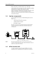
System Description autopilot data, mode keys and course adjust keys. It has two Robnet2 connectors for system interconnection and expansion and two SimNet connectors for control and data sharing with other Simrad products. A NMEA2000 Adapter Cable is available for interface through a SimNet port (page 84). 1.5 Autopilot Computer The autopilot computer is the heart in the AP16 autopilot system. It contains the steering computer, interface to other system components, and interface to Volvo Penta IPS system.
Simrad AP16 Autopilot 1.8 Software record When the system is switched on, a status display shows the software versions for the control unit and the autopilot computer. See page 12. Software version Description SW 1.2.
Operation 2 OPERATION WARNING ! An autopilot is a very useful navigational aid, but DOES NOT under any circumstance replace a human navigator.
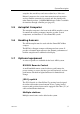
Simrad AP16 Autopilot The control unit shown above can operate as a stand alone unit in an autopilot system or combined in a multistation system. In a multistation system the command can easily be transferred from one unit to another. AP16 units not in control will display the icon. The AP16 system is capable of the following primary steering modes: STBY (power steering), AUTO and NAV, each mode having a dedicated push button.
Operation After approximately 5 seconds, the following message is displayed. The system is now operative and the unit that was turned on will show the Standby mode display. Other units in a multistation system will display "Inactive" and/or depending on model. Control is transferred to any single unit by pressing its’ STBY button. A long press (2-3 sec.) on the STBY button switches the system OFF and during this time, the alarm will sound.
Simrad AP16 Autopilot Flashing course knob icon When the PORT and STBD buttons are is used for settings etc., an icon will flash on the screen to tell that no course changes can be made unless you press the AUTO button. Alarms In the event there is an audible alarm with explaining text on the control unit, refer to section 6 Trouble shooting. 2.3 Non-Follow-Up steering (NFU) In Standby mode, the NFU display is presented when the PORT or STBD button is pressed.
Operation 2.4 R3000X Remote Control (NFU) SIMRAD Push button for Port and Stbd commands STBY-AUTO In STANDBY mode, the rudder will move as long as the Port or Stbd button is pressed. In AUTO mode the set course will change 1° each time the button is pressed. Note! STBY/automatic Automatic modes are active when the lamp is lit. Simrad R3000X If you keep the button pressed, it will automatically change the setting in increments of 3° per second. Mode changes are as per table below.
Simrad AP16 Autopilot Automatic steering mode Set course: 340 degrees Compass reading: 340°M Steering parameter: LO-A Rudder angle: 00° The AP16 will keep the boat on the set course until a new mode is selected or a new course is set with the PORT or STBD buttons. 1 Port course adjust, 1°/push 10 Port course change, 10°/push 10 Stbd.
Operation 2.7 Automatic control of steering parameters The AP16 provides two different sets of steering parameters for controlling the response of the boat at different speeds while in automatic modes. The autopilot selects the LO (response) steering parameters when engaging an automatic mode from STBY provided there is no speed input. This is a safety feature.
Simrad AP16 Autopilot To toggle between LO and HI parameters, press the "AUTO" button two times quickly. A AUTO Quick double press Notes ! 1. If you are in NAV or NoDrift modes you need not enter AUTO mode to manually change the parameter set. Just make a quick double press on the AUTO button. 2. The manually selected setting (HI or LO) will override the automatic selection and remain in effect until you re-enter any automatic mode from STBY. 2.
Operation 2.10 Dodge in AUTO Dodging is useful in situations where you need to quickly take control of the helm to steer around an obstruction, and then resume the previous set heading. Dodging is activated by a quick double press on the TURN/DODGE button. When in DODGE mode the displayed set course is the last one set prior to activating the dodge function.
Simrad AP16 Autopilot 2.11 NoDrift The NoDrift mode is an alternative to route steering in NAV mode, and is automatically entered when you press the NAV WIND button provided NoDrift has been selected in the (user) SETUP menu (page 27). The autopilot will steer to an imaginary waypoint and the bearing is the boat’s heading at the very moment the NoDrift mode is engaged. Unlike when in Auto mode the vessel will steer a course equal to the bearing line unaffected by wind and current (no drift).
Operation 2.12 Navigating with the AP16 The AP16 has the capability to use steering information from an external navigator (GPS, Chart Plotter) to direct the boat to a specific waypoint location, or through a route of waypoints. In the NAV mode, the AP16 uses the compass as heading source for course keeping. The information received from the navigator alters the set course to keep the boat on the track line and direct it to the destination waypoint.
Simrad AP16 Autopilot NAV If only one waypoint has been entered the bearing will be from the present position to the destination waypoint. Note ! NAV Note ! The prompt display shows the name of the next waypoint (WP), the bearing of the track line (BWW) from the previous waypoint to the destination waypoint, the required course change (CHG) and the direction in which the boat will turn. Press the NAV button again to accept the waypoint as the location to steer towards.
Operation NAV Alert screen. Press NAV button to verify course change larger than 10°. If no verification is received, the AP16 will continue on the current set course in AUTO mode. STBY Regain manual steering by pressing the STBY button Setting the waypoint arrival circle For route navigation it is recommended to use automatic waypoint shift/change at a set waypoint arrival circle. The arrival circle should be adjusted according to boat speed. The higher speed, the wider circle.
Simrad AP16 Autopilot Example: With the speed of 20 knots you should use a waypoint circle with radius 0.09 nm. Note ! 2.13 The distance between any waypoints in a route must not be smaller than the radius of the waypoint arrival circle when using automatic waypoint shift. Dodge in NAV The previous set course is stored by the AP16.
Operation 2.14 Selecting a different Navigation source If you have more than one navigation source connected to the AP16, you will be able to choose any for navigation. Refer to the ‘Source Select’ item in the User Set-up menu for details on selecting a different navigator (page 27). 2.15 Multiple station system In normal operation control is accessible from every control unit connected to the AP16 system. One control unit is "active" and provides the user with access to all functions.
Simrad AP16 Autopilot The "locked" control units in the system will show: The “Lock function is disengaged by one of the following actions: − The active control unit unlocks the other ones and makes them “inactive” by another double press on the STBY button. It also displays the icon before it returns to the normal active state. − The system is switched OFF by any control unit (press STBY for 2-3 seconds). 2.17 User Set-up Menu In the AP16, all modes except NFU have a complemental User Set-up menu.
Operation The backlight of the display and buttons may be adjusted to 10 levels (10 = brightest). The setting is stored when the system is turned off. Adjustment is local to the control unit you adjust or synchronized with other units in the Simrad Group (page 73). NAV source Select the source for NAV mode steering e.g. CP34. NAV WIND This setup will configure the active mode under the NAV WIND button. The following alternatives are available: • NAV (Ref page 21) • NoDrift (Ref.
Simrad AP16 Autopilot “SEARCHING” is flashing as long as the autopilot is searching. When the automatic interface setup is finished the display will read “DONE”. Press the mode button to leave the User setup. Manual source select Step through the list of sources using the PORT 1 or STBD 1 button. Select the wanted source by using the PORT 10 or STBD 10 button. – – indicates that no source is supplying the data available. Notes ! 1.
Operation Wind Angle Select the source for Wind Angle. Wind Calculated Select the source for Calculated Wind data. The autopilot uses internal source irrespective of the selected source. Water Speed Select the source for water speed (normally the same as the source providing Log data). Water temperature Select the source for water temperature (normally the same as the source providing depth data). DisLog Select the Log source. Depth Select the source for depth data.
Simrad AP16 Autopilot Contrast The contrast of the display may be adjusted to 10 levels (10 = highest contrast). The setting is stored when the system is turned off. Adjustment is local to the control unit you adjust. At high temperatures, not all levels are available due to automatic temperature compensation. Press the STBY button to leave the User setup. AUTO Mode Settings that are added for the AUTO mode are shown below. Other relevant settings are described under STANDBY mode in this chapter.
Operation Seastate filter OFF: Seastate filter is disabled. AUTO: Automatically reduces rudder activity and autopilot sensitivity in rough weather by an adaptive process (default). MANUAL: Manual yaw band adjust (1-10, 10 ≈ ±6°). The manual setting determines the number of degrees the vessel may deviate from the set course before any command is given to the rudder. The AUTO setting is recommended.
Simrad AP16 Autopilot 2.18 INFO menu A number of instrument pages are available under each mode screen if the required information is available on SimNet (see page 73). The INFO menu is accessed by a single press on the INFO/SETUP button (not necessary if the unit is inactive).
Operation True wind Wind angle Wind Speed VMG to wind Wind direction True wind speed Wind shift angle Track data Waypoint name Bearing Position – Waypoint Cross Track Error Nav data Waypoint name Bearing Position – Waypoint Course Over Ground Distance to waypoint Position Latitude Longitude Sea Temperature If you prefer not to have all instrument pages available in the INFO menu, you may remove pages under the User setup menu. See page 26.
Simrad AP16 Autopilot Course knob icon Initially when the INFO menu is accessed an icon will replace the mode index to tell that no course changes or other course related settings can be made unless you press a mode key. The icon will time out after 3-5 seconds and be replaced by the mode index. INFO menu flowchart 1 1 11 12 1 10 2 9 3 8 4 7 6 5 3-5 sec. time-out Toggle 1 3-5 sec.
Operation INFO menu and Main screen active unit INFO-menu Main screen 10 10 1 1 11 12 1 2 10 9 7 Note ! 3-5 sec. time out 3 4 8 6 5 Whenever the INFO menu is active and the mode index is present on an active unit, operating the PORT and STBD buttons will immediately make the main screen reappear. INFO menu and Main Screen, inactive unit Previous INFO page 1 1 Next INFO page Last shown INFO page You can view the INFO pages without activating the unit.
Simrad AP16 Autopilot This page is intentionally left blank 36 20222121A
Installation 3 INSTALLATION 3.1 General This section provides detailed information required to successfully installing the AP16 Autopilot system. The basic AP16 system includes only three modules that need to be mounted in different locations on the boat, and also need to interface with at least three different systems on the boat: − − − The Volvo IPS system The boats electrical system (input power) Other equipment on board (GPS/Chart plotter etc.
Simrad AP16 Autopilot e) Viewing parameters 9. Test Autopilot Operation at Sea (refer to Sea Trial instructions, pages 60, 74) 10. Provide the user with training (Page 75) 3.3 Unpacking and handling Care should be taken when unpacking and handling the equipment. A visual inspection should be made to see that the equipment has not been damaged during shipment and that all components and parts are present according to the packing list.
Installation 3.5 AP16 System Layout Figure 3-1 AP16 system layout with options 3.6 Autopilot computer installation The autopilot computer is designed to operate in a location with ambient temperatures below +55°C (+130°F). It must be mounted close to the Volvo Autopilot Interface within the length of the interconnection cable, 1 m (3’). See Figure 3-7. Note ! The autopilot computer unit is not weatherproof and should be mounted vertically in a dry environment.
Simrad AP16 Autopilot Grounding and RFI The autopilot system has excellent RFI protection. The autopilot computer should have a proper ground connection to the hull/bonding system. Robnet2 cables and other signal cables (Volvo IPS) should not be run in parallel with other cables carrying RF or high current, such as VHF and SSB transmitters, battery chargers/ generators, winches and thrusters.
Installation Screw the strain relief tab to the cable exit port on the autopilot computer unit using the screws supplied and secure the cables to the tab using the wraps as shown. Figure 3-3 Cable strain relief 3.7 Control unit installation Avoid mounting the control unit(s) where it is easily exposed to sunlight, as this will shorten the lifetime of the display. If this is not possible, make sure the units are always covered with the white protection cover when not used.
Simrad AP16 Autopilot − Connect the Robnet2 cable(s) to the control unit connector(s) Do not over-tighten the mounting screws! Optional bracket mounting − Locate the cradle on the mounting site and mark the 4 holes for the fixing screws on the mounting surface. The bracket can be mounted as shown on Figure 3-4 or 90° off. − Drill the 4 mounting holes and screw the cradle to the mounting surface. − Use the supplied screws to fasten the control unit to the left and right brackets.
Installation 3.8 ROBNET2 network cables As Robnet units have two Robnet2 connectors (blue) they can be used as "jack points" for further expansion of the system. There are no dedicated "in" or "out" connectors. You may connect the cables to any available Robnet2 connector (blue) on the specific unit. The Robnet2 connectors have a locking mechanism for extra safety. Caution ! Do not mix the blue Robnet2 cables with the yellow SimNet cables.
Simrad AP16 Autopilot Cable pairs 1. pair 2. pair Color code Signal Pink V SYSTEM+ Grey V SYSTEM– Brown Bus– White Bus+ Yellow On - Off Figure 3-6 Robnet2 Connector Note ! The connectors are weather proof according to IP65, when properly installed. All unused Robnet2 connectors must be fitted with the plastic cap to protect them against dirt and moisture. Figure 3-7 Control unit connection J1 and J2 (left) are Robnet2 connectors. J3 and J4 are SimNet connectors.
Installation AP27 connection If a Simrad AP27 is part of the system, use the JP27 Jack Point and connect as shown on Figure 3-5. Note ! 3.9 The AP27 cable contains an air-breathing tube. Check that the cable runs free to avoid blocking of the tube. RC36 Rate Compass installation Figure 3-8 RC36 mounting The heading sensor is the most important part of the AP16 system and great care should be taken when deciding the mounting location.
Simrad AP16 Autopilot When mounting RC36 on a bulkhead alongship, a +90° or –90° correction is needed dependent on whether it is port or starboard bulkhead. Note ! Offset correction is performed after the calibration (see paragraph 4.7). Find a location that provides a solid mounting place free from vibration, and as close to the vessel's centre of roll and pitch as possible, i.e. close to the water line. It should be as far as possible from disturbing magnetic influences such as the engines (min.
Installation 3.10 R3000X Remote Control installation R3000X should be mounted in the supplied bracket that can be fixed by four mounting screws. The unit is weather proof and can be mounted outdoor. R3000X REMOTE CONTROL AUTOPILOT COMPUTER TB1 TB2 NFU 4 STBD Yellow LAMP Green Red Blue GND PORT 1 Figure 3-10 R3000X connection 3.11 JS10 Joystick Refer to separate installation instructions supplied with the JS10 Joystick. 3.
Simrad AP16 Autopilot S35 STEERING LEVER AUTOPILOT COMPUTER TB1 TB2 NFU 4 STBD Yellow LAMP Brn/Wh Pnk/Gry Green GND PORT 1 Figure 3-11 S35 connection The unit is opened by removing the three screws on the back cover. Inside are two sets of micro-switches, a printed circuit board with a plug-in terminal and a jumper strap. 3.13 Interfacing With the AP16 autopilot system there are several possibilities to connect to other equipment for data collection and exchange: 1. Use SimNet 2.
Installation SimNet network cables A SimNet unit has one or two yellow SimNet connectors. There are no dedicated “in” or “out” connectors. Find the shortest and easiest way to route the SimNet cables from product to product and select the standard length cables from the SimNet accessory program. SimNet cables are available in 0.3 m (1 ft.), 2 m (6.6 ft.), 5 m (16.6 ft.) and 10 m (33 ft.) length all with plugs at both ends.
Simrad AP16 Autopilot COM BI DATA COM BI SIM RAD IS12 SIM RAD IS12 SIMRAD IS12 STBY ALARM TIMER UPPER INFO L OWER INFO LIGHT ALARM TIM ER UPPER INFO LOWER INFO LIGHT PAGE UPPER INFO LOWER INFO 10 10 AUTO PWR LIGHT INFO SETUP NAV WIND 1 1 TURN DODGE Figure 3-12 SimNet network, small system COM BI DATA COM BI SIMRAD IS12 SIMRAD IS12 SIM RAD IS1 2 STBY PWR LIGHT ALARM TIM ER UPPER INFO LOWER INFO LIGHT ALARM TIM ER UPPER INFO LOWER INFO LIGHT PAGE UPPER INFO LOWER
Installation COM BI COM BI SIM RA D IS1 2 LIGHT ALARM TIMER UPPER INFO LIGHT ALARM TIM ER UPPER INFO SIM RAD IS12 SIM RA D IS1 2 SIM RAD IS12 LOWER INFO DATA COM BI LOWER INFO LIGHT ALARM TIMER UPPER INFO LOWER INFO LIGHT PAGE UPPER INFO LOWER INFO STBY PWR AUTO NAV WIND DODGE INFO Figure 3-14 SimNet network, medium system Notes ! 1. Maximum total length of SimNet cable is 40 m (130 ft.) excluding the 30 m (99 ft.) of masthead cable. 2.
Simrad AP16 Autopilot Figure 3-15 Robnet2 and SimNet network * The wind transducer has a built in terminator 52 20222121A
Installation Figure 3-16 Robnet2, SimNet and Roblink network Notes ! 1. Maximum total length of SimNet cable is 60 m (196 ft.) excluding the 30 m (99 ft.) of masthead cable. 2. It is not necessary to connect all autopilot control units to SimNet for data sharing. However, if you want to have full redundancy and SimNet control, e.g. select sources, you have to connect the actual unit to SimNet. 3. AT15 is a NMEA0183/SimNet converter for the IS15 Instrument system. IS15 makes no load on SimNet. 4.
Simrad AP16 Autopilot 3.15 Radar Clock/Data Heading Output SIMRAD/ANRITSU OR FURUNO RADAR AUTOPILOT COMPUTER TB4 R ADAR 4 DATA H DATA L CLK L CLK H 1 Figure 3-17 Radar Clock/Data connection 3.16 IS15 Instrument installation For installation and operation of the IS15 instruments refer to separate manuals. For interfacing the IS15, you need the dedicated AT15 Active Tee as an interface item (pages 53, 84). 3.
Configuration and setup 4 CONFIGURATION AND SETUP 4.1 First time turn on Before attempting to turn on the AP16 and perform an Installation Setup, the hardware installation and electrical connections must be completed in accordance with the installation instructions. The design of the AP16 includes advanced features that have simplified the installation and setup of an autopilot. This is the start-up screen that is presented the first time you turn on your autopilot by pressing the STBY/PWR button.
Simrad AP16 Autopilot 4.2 Note ! Description of Installation Settings The installation settings must be performed as part of the installation of the AP16 system. Failure to do so correctly may prohibit the AP16 from functioning properly! The Installation menu can only be accessed in STBY mode.
Configuration and setup − The Installation Settings are global except for display units and language, enabling settings to be distributed to all control units in the system. 4.3 Installation Menu The Installation Menu is presented on the autopilot display by pressing and holding the INFO/SETUP button for 5 seconds. Note ! The INSTALLATION MENU is different from the USER SETUP MENU. Refer to the flow diagram on the next page for a pictorial view of the Installation Menu.
Simrad AP16 Autopilot INSTALLATION MENU ENTER INSTALLATION MENU BY PRESSING AND HOLDING THE NAV BUTTON FOR 5 SECONDS SYMBOLS 10 SELECT OR CONFIRM 10 LANGUAGE MENU 10 LANGUAGE ENGLISH DEUTSCH FRANCAIS 10 ESPANOL ITALIANO NEDERLANDS SVENSKA NORSK 1 1 Mode in STBY ? REVERT TO PREVIOUS MENU ITEM 1 10 1 INTERFACE MENU 10 Yes PROCEED TO NEXT MENU ITEM BY PRESSING STBD 1 BUTTON 1 INTERFACE RADAR Ou t pu t 1 No 1 DISPLAY UNITS 1 WIND SPEED WATER TEMP DEPTH 10 1 1 DISPLAY UNITS 1 1
Configuration and setup Language selection To access the language selection in the Installation Menu, confirm “Yes” by pressing the STBD 10 button. The AP16 can present the display text in eight different languages: English, Deutsch, Francais, Espanol, Italiano, Nederlands, Svenska and Norsk. Press the STBD 10 or PORT 10 buttons to select language. Continue to next item in the menu by pressing the STBD 1 button, or leave the menu by pressing the STBY button. 4.
Simrad AP16 Autopilot Depth. Use the STBD 1 button to select an item and the STBD 10 button to select the unit. Available units are: Wind Speed: Knots (kt) (default) or meter/second (m/s) Sea temperature: Fahrenheit (°F) (default) or Celsius (°C) Depth: Meter (m) (default) or feet (ft) Exit the Display units menu by pressing STBD 1 button to proceed to the Sea trial menu, or press STBY to return to normal AP16 operation. 4.
Configuration and setup − Init NAV (to set the response you prefer when steering onto a track in NAV mode) − NAV change limit (the limit of the automatic course change at the approaching waypoint) Select Seatrial by pressing the STBD 1 button and confirm by pressing the STBY 10 button. Compass calibration This function will activate the compass calibration procedure for Simrad compasses connected to Robnet2 and the Autopilot Computer terminals (HS). Notes ! 1.
Simrad AP16 Autopilot 3. Confirm start of calibration by pressing the STBD 10 or PORT 10 button. The display will flash “Calibrating”. Establish your turning rate using the arrows in the display. 4. When the calibration is completed, (after having made approximately 1 1/4 turns), it will be confirmed by the display reading “Confirmed”. Compass deviation The heading from a magnetic heading sensor will normally have a deviation when compared with the actual direction of the earth’s magnetic field.
Configuration and setup Compass Offset After calibration, also check the compass readout against a known reference, a compensated compass or a bearing. If the reading has a fixed offset, proceed to next menu item by pressing STBD 1 button or return to STANDBY mode by pressing the STBY button. Note ! Offset correction is always performed after the calibration. If you use COG as a reference for the offset remember it has to be a magnetic reading.
Simrad AP16 Autopilot Wind Offset Note ! This offset only applies if you have a wind transducer directly connected to SimNet (IS12TW) or a wind transducer that outputs data on NMEA2000 format. The Wind Offset feature allows you to correct for a fixed wind angle offset. Steer the boat directly into the wind with a damping of 15s. Keep the bow at a steady heading for 15-20 sec. and read the wind angle.
Configuration and setup NMEA0183 sentence ‘DBT’ contains no depth offset and the reading will be from the position of the transducer. When the depth offset is set to zero, the indicated depth is from the transducer to the bottom. To read the depth from the water surface to the bottom you have to set the depth offset according to the vertical distance between the surface and the transducer, positive (+) value.
Simrad AP16 Autopilot WARNING ! The Automatic tuning function will take control of the boat and perform a number of S-turns. It must always be performed in open waters at a safe distance from other traffic. The Automatic tuning function may take from 1 to 2 minutes to complete. To stop the Automatic tuning, press the STBY button. Activate the Automatic tuning, by pressing the STBD 10 button. The display will flash “Automatic tuning”.
Configuration and setup Use the STBD 10 button to set the transition speed to the wanted value in knots. Range: OFF – 30 knots Default: 5 kts Proceed to next menu item by pressing STBD 1 button. Init NAV Sets a firm or soft approach to the track line when entering the NAV mode at the first leg. The approach angle is dependant (adaptive) on the distance (XTE) from the track line and the boat speed. Select firm or soft approach to the track line using the STBD 10 or PORT 10 button.
Simrad AP16 Autopilot 4.7 Parameters To access the Parameters, press the STBY 10 button. A boats steering parameters found by the Automatic tuning can be looked at and if needed changed under this menu item. The steering parameters can also be set manually instead of performing an Automatic tuning. The parameters are divided into two sets (page 17): • HI value parameters for automatic steering at low speed. • LO value parameters for automatic steering at high speed.
Configuration and setup The two most important parameters that determine the performance of the automatic steering are Rudder and Counter Rudder. Rudder sets the rudder gain which is the ratio between the commanded angle and the heading error. Course to steer Too little Rudder Course to steer Too much Rudder − − − Too little Rudder and the autopilot fail to keep a steady course. Too much Rudder gives unstable steering and reduces speed. Low speed requires more rudder than high speed.
Simrad AP16 Autopilot New course Correct setting of counter rudder, ideal response Autotrim standard value is 40 sec. which should work well on most boats. Recall Autotuned? To recall the parameter values that were achieved during the Automatic tuning procedure, press the STBD 10 button. When parameter values are recalled, Confirmed is displayed. Exit the Parameter menu by pressing STBD 1 button to proceed to the Service menu, or press STBY to return to normal AP16 operation. 4.
Configuration and setup Select System data by pressing the STBY 10 button. System Data Menu Steer compass Steering Compass readout, M=Magnetic, T=True Rudder Rudder angle. Between zero and 26 degrees. Input voltage Mains voltage on input terminals. To exit the menu, press any mode key (STBY, AUTO or NAV). SimNet Data Screen Select STANDBY mode. Press en hold the NAV/WIND button for 5 seconds to enter the Installation Menu. Press the STBD 1 button to select "SERVICE".
Simrad AP16 Autopilot Decoding The incoming signals are decoded according to a built in priority table in the AP16. For all data items, one of the following codes will be displayed: ––– No data or no NMEA sentence containing the data needed is available at the input port. OK Valid data found INV Message with invalid information.
Configuration and setup SimNet setup Select the SimNet setup menu by pressing the STBD 1 button and confirm this by pressing the STBD 10 button. Sn 00000 is the unique SimNet ID number for the specific autopilot control unit. Group selection SIMRAD: Autopilot is part of the Simrad Group. Source selection will be common for the products in the group (synchronized). STAND ALONE: Source selection for the autopilot will not be transferred to other products in the Simrad Group (no synchronization).
Simrad AP16 Autopilot Global SimNet reset Resets the entire SimNet setup in the Simrad Group and initiates a new automatic interface setup. See chapter 4.1. Master Reset Note ! A Master Reset is part of the final test at the factory, which will reset the memories to factory settings. Unless you need to clear all stored values during the installation setup procedure, you should not perform a Master Reset. The Master Reset needs a double confirmation to prevent an accidental reset.
Configuration and setup transition speed is crossed (by more than 1 Knot higher or lower speed). − Try the Dodge and U-turn function. − If a Non-Follow Up lever (or handheld remote) is connected, test change of modes and verify port and starboard steering commands of the lever. − Set waypoints into each navigator connected to the system, and verify that the AP16 steers in NAV mode for each NAV source. − Try the NoDrift mode. − Provide the owner with user training.
Simrad AP16 Autopilot − Locating the Mains circuit breaker and the separate SimNet circuit breaker if provided.
Maintenance 5 MAINTENANCE 5.1 Control unit The AP16 Control Unit will under normal use require little maintenance. If the unit requires any form of cleaning, use fresh water and a mild soap solution (not a detergent). It is important to avoid using chemical cleaners and hydrocarbons such as diesel, petrol etc. Make sure that all open Robnet2 connectors are fitted with a protection cap. It is advisable at the start of each season to check all connections to the control unit head.
Simrad AP16 Autopilot 5.4 Exchange of software programme You will need a special kit for a PC to perform the programming of the AC05 Autopilot Computer and the AP16 Control Unit. Order the following from Simrad: Programming kit P/N 22088595. Instructions are included. Autopilot Computer Remove the bottom cover to get access to the software download connector.
Trouble shooting 6 TROUBLE SHOOTING An autopilot is a complex system. Its performance dependents on a proper installation and a successful sea trial. In the event of an autopilot failure, the AP16’s numerous test features will assist you in isolating a probable fault. Audible and visual alarm is provided for every fault being detected. The audible alarm is reset by pressing any button (e.g. by changing mode from AUTO to STANDBY).
Simrad AP16 Autopilot Display readout Shallow water (Only if AP25 is part of the system) Compass data missing No connection with IPS system Failure active Control Unit 80 Probable fault Recommended action The depth is inside 1. Carefully observe the actual the set limit or outside depth. the range. 2. Adjust the alarm limit if not Depth data is missing. hazardous. 3. Steer to safe depth, the alarm will reset automatically. 4. Turn off the shallow alarm if data is missing. No data from selected 1.
Trouble shooting Display readout Probable fault Recommended action ACXX high temp. Excessive temperature inside Autopilot Computer Switch off autopilot Memory failure ACXX Wrong checksum on memory parameters or variables. Autopilot Computer will use default values. Perform a "Master reset". Switch off and on again. If the alarm is repeated, replace Autopilot Computer PCB. Com. failure with Faulty Autopilot ACXX Computer or poor Robnet2 cable connections from the same. Low supply voltage 1.
Simrad AP16 Autopilot This page is intentionally left blank 82 20222121A
Spare parts list 7 SPARE PARTS LIST AP16 Control Unit 22087399 AP16 Control Unit 22088207 AP16 mounting kit consisting of: 22087589 Gasket 22084529 Cabinet corner 44165181 Screw 3,5x19 44165645 Screw 3,5x32 22088249 Optional mounting kit consisting of: 44141778 Screw M4x12 22087621 Cradle 22087605 Right bracket 22087613 Left bracket 22084859 Locking knob 44163145 Locking washer for left and right bracket 44163160 Cradle, locking washer 22087514 AP16 Sub Ass’y (incl.
Simrad AP16 Autopilot 44135333 22089304 Plug-in Terminal 2-way AC05 Software RC36 Rate compass 22086920 22081442 22086938 24005647 RC36 Rate Compass Installation Accessories Consisting of: 20104972 Mounting plate (2) 44140762 Screw 3.
Spare parts list 20222121A 85
Simrad AP16 Autopilot 8 TECHNICAL SPECIFICATIONS 8.1 AP16 Autopilot System Boat size and type:..................... Up to 80 feet, Power, Displacement, Sail Steering system types: ............... Volvo Penta IPS Inter-unit connection: ................ ROBNET network or two-wire supply/data System ON/OFF: ....................... From control units Supply voltage:.......................... 12 or 24 VDC Power consumption: ..................
Technical specifications Instrument screen NMEA0183 messages and SimNet MAIN (HDG+RUDDER) ROBNET2 PROPRIETARY, NMEA HDT and HTG, SimNet SPEED/DEPTH VHW + DBT/DPT, SimNet APPARENT WIND MWV, SimNet TRUE WIND/WIND DIRECT. MWV + VTG/RMC; SimNet POSITION GGA/RMC, SimNet NAV/TRACK DATA APB + VTG/RMC + GGA/RMC + RMB/BWC, SimNet LOG/SEA TEMPERATURE VLW + MTW, SimNet Note ! 8.2 Alternative messages are separated by slashes. AP16 Control Unit Dimensions: ...............................
Simrad AP16 Autopilot Figure 8-1 AP16 Control Unit – dimensions (Mounting bracket is optional equipment) 8.3 AC05 Autopilot Computer Dimensions: ............................... See Figure 8-2 Weight: ...................................... 1,1 kg (2,4 lbs) Supply voltage:.......................... 10.8 - 31.2V DC Reverse voltage protection ........ Yes Environmental Protection:......... IP22 Safe distance to compass: .......... 1.0 m (3 ft.) Power consumption: ..................
Technical specifications External Alarm: ......................... Open collector Temperature range: Operation: ......................... 0 to +55 °C (+32 to +130 °F) Storage: ............................. –30 to +80 °C (–22 to +176 °F) Mounting: .................................. Bulkhead mount Material:..................................... Epoxy coated silumin and ABS Number of control units: ........... 7 Input for NFU control:............... Yes Radar clock/data interface .........
Simrad AP16 Autopilot 8.4 RC36 Rate compass Dimensions: ............................... See Figure 8-3 Weight: ...................................... 0,9 kg (2,0 lbs) Supply and interface:................. Robnet Power consumption: .................. 0,9 watts Automatic Performance: Calibration: ....................... Automatically activated by control head Gain compensation: .......... Automatically adjusted continuously Rate sensor stabilized heading output Accuracy:...................................
Technical specifications 8.5 R3000X Remote Control Dimensions: .... See Figure 8-4 Weight:............ 0,4 kg (0,9 lbs) Material:.......... Epoxy coated aluminium Protection ........ IP56 Safe distance to compass: 0.15 m (0.5 ft.) Temperature range: Operation: ...–25 to +55 °C (–13 to +130 °F) Storage: .......–30 to +70 °C (–22 to + 158 °F) Cable length: ... 7 m, shielded Mounting bracket:....... Supplied Figure 8-4 R3000X - Dimensions 8.6 JS10 Joystick Dimensions: .....................................
Simrad AP16 Autopilot 8.7 SimNet Maximum number of products connected in a network:...................................... 50 Maximum cable length: ............. .........................................................120 m (400’) Bit rate of the bus: ..................... ....................................................250 Kbit/second Maximum DC current through a single SimNet plug ......................................... 5A SimNet power supply: ............... .....................................
Technical specifications 8.8 IP protection Each part of a Simrad autopilot system has a two digits IP protection code. The IP rating is a method to classify the degree of protection against solid objects, water ingress and impact afforded by electrical equipment and enclosures. The system is recognised in most European countries and is set out in a number of British and European standards.
Simrad AP16 Autopilot 8.
Technical Specifications Remarks: AP26 Out Gateway C AP25 N AP16 127237 N N 65408* 65357* 129284 129283 Indata use d d d x d d d x d d d d d d d d d d d d x x x x d d d x In INFO views Depth+Offset is displayed if x offset is present d d d d d d x x x d d d d d d d d d d d d d d d d d d d d d d d d d d d d 1 1 1 1 1 1 1 x* x* x* 20222121A x * SimNet proprietary x x x x x x x x x x x x *Only transmitted if NMEA183/RC36/RFC35 is source 95
Simrad AP16 Autopilot 9 GLOSSARY Apparent wind – The speed and direction from which the wind appears to blow with reference to the bow when the boat is moving (also called relative wind). Arrival alarm – An alarm signal issued by a GPS/chartplotter that indicates arrival at or at a predetermined distance from a waypoint. (see arrival circle). Arrival circle – An artificial boundary placed around the destination waypoint of the present navigation leg, the entering of which will signal an arrival alarm.
Glossary Magnetic variation - A magnetic compass points to the magnetic north pole. The difference between this direction and true north is the magnetic variation. The amount and direction of this variation is dependent upon where on the earth you are located. NMEA0183 - A format (language) designed to permit communication between various types of marine electronic equipment. In essence this is a two-wire shielded, serial data link, permitting one device to talk while other devices listen.
Simrad AP16 Autopilot True bearing – Bearing relative to true north; compass bearing corrected for compass error. True heading – Heading relative to true north (the meridian). Waypoint - A discrete point, stored in a navigator, located on the surface of the earth. Normally this point will be identified by Lat/Lon coordinates although in some systems it may be shown by T.D.'s. XTE - Cross Track Error - Used to identify a vessels position relative to a straight line drawn between two waypoints.
Index 10 INDEX A alarm external, 54 listing, 79 apparent wind, 96 arrival circle, 23 auto setup, 55 automatic tuning, 65 autopilot computer installation, 39 maintenance, 77 specifications, 88 depth offset, 64 depth source, 28 display units, 59 dodging, 19 dodging in Nav mode, 24 F fluxgate compass installation, 45 G grounding, 40 autotrim, 70 I B illumination.
Simrad AP16 Autopilot reset, 73 setup, 73 specifications, 92 N NAV change limit, 22, 67 NAV source, 27, 28 navigating, 21 NFU Steering lever, 9, 15 NMEA data, 71 NMEA messages, 94 NoDrift, 20 P parameter adjust, 68 Simrad group, 73 software program exchange, 78 software setup, 55 source manually update, 28 source select, 27 source update, 27 specifications, 86 steering lever parameter selection automatic, 17 manual, 18 installation, 47 system basic, 8 components, 8 specifications, 86 with options, 39
AP16 manual for Volvo Penta IPS system EN, Doc.no.20222121, Rev.