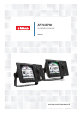
AP70/AP80 Installation Manual ENGLISH navico.
Preface Disclaimer As Navico is continuously improving this product, we retain the right to make changes to the product at any time which may not be reflected in this version of the manual. Please contact your nearest distributor if you require any further assistance. It is the owner’s sole responsibility to install and use the equipment in a manner that will not cause accidents, personal injury or property damage. The user of this product is solely responsible for observing safe boating practices.
Warranty The warranty card is supplied as a separate document. In case of any queries, refer to the our websites: www.navico.com/commercial and www.simrad-yachting.com. About this manual This manual is a reference guide for installing and commissioning the Simrad AP70 and AP80 Autopilot Systems. The manual will be continuously updated to match new sw releases. The latest available manual version can be downloaded from our web sites.
Contents 7 Introduction 7 7 7 11 12 14 Wheelmark approval Spare parts and accessories System overview Autopilot Control units Autopilot computers Computer boards 17 Mounting 17 17 17 20 General Mounting location AP70 and AP80 control units Autopilot computers 21 Wiring 21 21 22 23 25 25 26 26 27 28 33 35 36 39 39 40 40 Wiring guidelines The autopilot system, basic wiring principles The CAN bus Power supply FU80, NF80 and QS80 Remote control units Steering levers NMEA 2000 and SimNet devices IEC61
| 66 Installation checklist 66 66 67 69 General Checklist Installation settings Installed unitsw 70 Specifications 70 71 72 74 77 78 AP70 and AP80 Autopilot system AP70 and AP80 Control units Autopilot Computers Computer boards AP70 and AP80 Connector pinouts Supported data 79 Drawings 79 80 81 81 82 82 AP70 Control unit AP80 Control unit AC70 and SI80 Computer SD80 and AD80 Computers AC80A and AC80S Computer AC85 Computer Contents | AP70/AP80 Installation Manual
1 Introduction Wheelmark approval The AP70 and AP80 systems are produced and tested in accordance with the European Marine Equipment Directive 96/98. This means that these systems comply with the highest level of tests for non-military marine electronic navigation equipment existing today.
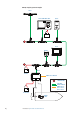
AP70, simple system example HS70 QS80 AP70 CONTROL UNIT CMD MENU TURN STBY AUTO NAV WORK 12/24V DC T NSE RC42N T AC70 12 V DC NMEA 0183 IN/OUT T TERMINATOR CAN BUS DROP CABLES NMEA 0183/ IEC 61162-1/ IEC 61162-2 12/24V DC DRIVE UNIT 8| Introduction | AP70/AP80 Installation Manual
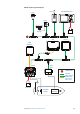
AP80, simple system example NF80 GS15 AP80 CONTROL UNIT CMD MENU CDI80 STBY AUTO NAV ALARM TURN WORK CD100A 12/24V DC T NSO IS70/80 GYRO COMPASS AC80S AD80/ SD80 T T TERMINATOR CAN BUS DROP CABLES NMEA 0183/ IEC 61162-1/ IEC 61162-2 12/24V DC SOLENOID VALVES Introduction | AP70/AP80 Installation Manual THRUSTER CONTROL |9
AP80, Wheelmark-approved system example ¼¼ Note: For IMO approval, other equipment must be connected via an SI80 board located in an SI80, AC80A, AC80S or AC85 computer.
Autopilot Control units Front - controls 1 2 3 STBY 8 ¼¼ * AUTO NAV TURN WORK 4 6 7 14* 12* ALARM 5 MENU ALARM CMD 9 10 11 12* 13* Available on AP80 control units only. No. Key/Description 1 CMD/THRUSTER. A short press takes/requests command. A long press (3 seconds) activates/deactivates available thrusters 2 MENU. A short press displays the active steering mode’s quick menu. A second click displays the Settings menu 3 POWER/LIGHT. A short press displays the Light dialog.
Rear - connectors 1 No. SD80 AD80 AC70 SI80 2 3 Connector/Description 1 4 pin connector for 12/24 V DC local power, External alarm/Active unit OUT 2 Micro-C connector for CAN bus 3 Ethernet network port, used for sw update Autopilot computers The AP70/AP80 systems use a combination of 5 different enclosures and 4 boards to form a flexible computer and interface system. There are 7 standardized and 1 customized computers with built-in and optional boards as shown below.
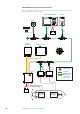
Autopilot Control unit GPS Sensor Compass SG05 PRO AC80A Kit (000-11483-001) and SG05 PRO AC80S Kit (000-11484-001) AC80S / AC80A T 2 1 T SG05 PRO (000-11479-001) 3 CAN BUS compatible steering system Item 12/24 V DC 4 Thruster control Description 1 Micro-C backbone 2 Micro-C T-joiners 3 SimNet to Mircor-C (male) Drop cable 4 SD05 Cable, female T Terminators ¼¼ Notes: -- For IMO approval, the system must contain AC80S or AC80A Computer.
Computer boards Indicator diodes and switches POLARITY CHECK Indicator diodes and switches are available on the boards as shown in the tables below.
AD80 board AD80 AC70 AC80A AC85 AC85 • • • • • • • • Drive computer board for rudder or thruster, supporting analog voltage or low current signals for SD80 angle or proportional SI80 control.
SI80 board SD80 SI80 AC80S AC80A AC80S AC85 AC85 • • • • • A four channel NMEA 0183 interface computer board and voltage supply for CAN bus. Includes: SIMNET TERMINATION - Switch for CAN bus termination ON/OFF SIMNET - SimNet 15 V out REMOTE - Input for NFU steering lever NMEA 0183 CH..
2 Mounting General Mechanical installation of optional equipment are described in separate manuals following the units. These manuals can also be downloaded from out websites: www.navico.com/commercial and www.simrad-yachting.com. Mounting location The units should be mounted with special regard to the units’ environmental protection, temperature range and cable length. Poor ventilation may cause the units to overheat. wRefer “Specifications” on page 70.
Panel (flush) mount 1. Attach the mounting template to the selected mounting position 2. Drill pilot holes for the 4 hole saw cuts and for the 4 self tapping screws used to secure the unit. If using M4 machine screws use a 5 mm (0.20 ”) drill bit 3. Use a 25 mm (1 “) hole saw to cut the four corner radius 4. Cut along the dotted line and remove waste material 5. Peel backing off the gasket and apply it to the unit (A) 6. Connect the cables to the rear of the unit before placing the unit into the console 7.
Bracket mount (option) ¼¼ Note ! When the control unit is bracket-mounted, it is not weatherproof from the back due to a breathing hole in the back cabinet. When bracket-mounted, the exposed parts of the plugs should be protected against salt corrosion. 1. Use the bracket base as a template to mark the screw hole location 2. Drill pilot holes and hole for cables if required 3. Secure the bracket base to the surface 4.
Autopilot computers The mounting location must allow for required working area when connecting the cables. Also ensure that the location for the computer units allows viewing the board’s LED indicators. The mounting surface needs to be structurally strong, with as little vibration as possible. If possible mount the unit close to the edges of a panel to minimize vibration. Ensure that any holes cut are in a safe position and will not weaken the boat’s structure. If in doubt, consult a qualified boat builder.
3 Wiring Wiring guidelines CAN network cables and other signal cables (i.e. compass, feedback, NMEA) should not be run in parallel with other cables carrying radio frequency or high current, such as VHF and SSB transmitters, battery chargers/generators, and winches. Don’t make sharp bends in the cables, and avoid running cables in a way that allows water to flow down into the connectors. If required, make drip and service loops.
The CAN bus The CAN bus is based on the well known SimNet plug & play concept and on the NMEA 2000 SAE J1939 protocol. Hard wiring is based on standard NMEA 2000 cables with Micro-C type connectors and joiners. The bus consists of a linear backbone using drop cables and Micro-C T-joiners for connecting NMEA 2000 and SimNet devices. The bus has a maximum cable length of 150 m (500 ft), and a drop cable has a maximum length of 6 m (20 ft).
Terminating the CAN bus ON OFF The CAN bus must have a terminator at each end of the backbone. In a default autopilot system the CAN bus expands from the AC80A, AC80S or AC85 Autopilot computer. This computer includes a terminator on the SI80 board, enabled by the micro switch. -- Set the switch to ON when the SI80 board is at the end of the CAN bus -- Set the switch to OFF when the SI80 board is used as additional power supply to the CAN bus Factory default setting of SI80 terminator is OFF.
12/24V DC T T 12/24V DC SI80 12/24V DC Network LEN When you have a larger system with network power in center of the backbone you should make the installation such that the load/current draw from the devices in each side/branch is equal. For LEN numbers, see “Specifications” on page 70. ¼¼ Note: 1 LEN (Load Equivalency Number) equals 50 mA current draw.
Powering the AP70 and AP80 control units The AP70 and AP80 control units are powered directly from a 12 V DC or 24 V DC source. The units are protected against reverse polarity, under voltage and over voltage. Power cable connector (female) 4 1 Key Color Description 3 2 1 Black Battery (-) 2 Blue 1 Alarm/Active 3 Yellow External command 4 Red Battery (+), 12 - 24 V DC 8 1 4 3 ¼¼ Note: It is recommended to install an external on/ off switch for power.
NMEA 2000 and SimNet devices NMEA 2000 devices can be connected to the CAN bus providing they are NMEA 2000 certified, meet the CE, FCC regulations and do not exceed the load specification. NMEA 2000 devices and SimNet devices with Micro-C connectors connects directly to the CAN bus backbone using drop cables and Micro-C T-joiners. ¼¼ Note: It is recommended to use a gateway when connecting non-Simrad units to the CAN bus backbone.
Autopilot computers Grounding The autopilot system has excellent radio frequency interference protection and all units use the autopilot computers as a common ground/shield connection. The units must therefore have a proper ground connection to the hull.
Mounting and Interconnecting the boards in the AC85 Computer The AC85 computer is delivered with one SI80 board. The SI80 board is not mounted from factory. Optional boards are ordered separately. The boards should be located as shown on the illustration, and secured to the computer base with the supplied screws and washers. A detailed mounting description is included with the AC85 computer. The document can also be downloaded from out web site.
Rotary drive Connects to: AC70 board (in AC70 or AC85 Computer). Rotary drive (reversible motor with clutch) is normally used for mechanical connection to Voith Schneider drive system or helm unit on sailing vessels. The rotary drive need connection to the Engage terminal for clutch operation.
Externally powered solenoids, common negative Connects to: SD80 board (in SD80, AC80S or AC85 Computer). SOLENOID VALVE SOL2 + POWER SOL1 SD80 BOARD SD80 , AC80S or AC85 Computer SOL1LO SOL1HI SOL2LO SOL2HI SOL2LO SOL1LO SOL1HI / SOL2HI SOLENOIDS FUSE 10A Externally powered solenoids, common positive Connects to: SD80 board (in SD80, AC80S or AC85 Computer).
Internal voltage control A nominal 0±10 V DC control signal is available for control. This voltage is galvanic isolated from the operating voltage for the autopilot. Rudder zero voltage and control range can be adjusted in the Dockside Drive setup. See “Rudder feedback/tunnel thruster feedback calibration” on page 51 . U_CTRL EXT READY INT ON For Analog output, internal voltage, the switch must be set to INT.
Voltage control with external reference, positive variable Normally used to control proportional valves with 12 V and 24 V power. Available control range will be from 5-95% of external voltage. Control signal will be positive variable relative the external reference voltage minus. Zero output = External power/2. Zero setting and control range output at U_CTRL can be adjusted in dockside setup. See “Rudder feedback/tunnel thruster feedback calibration” on page 51 .
Rudder feedback RF300, RF45X Connects to: AC70 board (in AC70 or AC85 Computer), SD80 board (in SD80, AC80S or AC85 Computer) or AD80 board (in AD80, AC80S or AC85 Computer). RF300 = White and Brown wires RF45X = Red and Blue wires ¼¼ Note: Polarity independent.
Current feedback input Connects to: SD80 board (in SD80, AC80S or AC85 Computer) or AD80 board (in AD80, AC80S or AC85 Computer). CURRENT FEEDBACK INPUT AD80/SD80 BOARD U_IN RANGE +20V +10V +5V COM 4 - 20 mA I_IN AD80/SD80, AC80S or AC85 Computer COM I_IN U_IN RUD_UI External feedback pot.meter input Connects to: SD80 board (in SD80, AC80S or AC85 Computer) or AD80 board (in AD80, AC80S or AC85 Computer). AD80/SD80 BOARD U_IN RANGE EXTERNAL FEEDBACK POT.
Alarm interface External alarm An external alarm can be connected to the autopilot control head. The alarm signal have an open contact for an alarm buzzer or an external alarm relay as illustrated below. The alarm voltage is the same as the main supply voltage. The maximum load on the external alarm output is 0.75 Amp. Alarms are configured globally in the system, i.e. they can be configured on one unit and seen, heard and acknowledged from all control units.
External I/O Handshake Connects to: SD80 board (in SD80, AC80S or AC85 Computer) or AD80 board (in AD80, AC80S or AC85 Computer). The SD80 and AD80 boards have two identical galvanic isolated handshake digital I/O ports that can be sw configured for various applications like interface to steering gear control, hand steering override, watch alarm, direct i/o type central alarm panel, pulse log input and pendulum ferry function. EXTERNAL INTERFACE AD80/SD80 BOARD HS..
AD80/SD80 BOARD HS.. OUT A OUT B IN + 1 4 3 RET + _ 2 AD80/SD80, AC80S or AC85 Computer HS.. 12 - 24 V DC CENTRAL ALARM PANEL BATTERY+ (12 - 24 V DC) OUT A OUT B IN + ALARM RET Description 1 Black Battery (-) 1 2 Blue Alarm/Active 2 3 Yellow 4 Red External command 1 8 Battery (+), 12 - 24 V DC Engage signal Connects to: AC70 board (in AC70 or AC85 Computer) or SD80 board (in SD80, AC80S or AC85 Computer).
SD80 BOARD SD80, AC80S or AC85 Computer 10 mA - 3 A + POWER + CMD RET RET + CMD ENGAGE Ready signal Connects to: SD80 board (in SD80, AC80S or AC85 Computer ) or AD80 board (in AD80, AC80A or AC85 Computer). The Ready signal is given when the autopilot system is operative for taking control. In case of serious software or hardware failure and when the system is turned off, the signal line will open.
External system selection Connects to: SD80 board (in SD80, AC80S or AC85 Computer ) or AD80 board (in AD80, AC80A or AC85 Computer). The system select (Sys sel) input signal can be used to alternate between the vessel’s own manual steering system and the autopilot system from an external system selector. Refer to IMO resolution MSC 64, sec. 4. A closing contact between the SYSSEL and RET terminals will disengage the autopilot from the vessel’s steering system.
ECDIS system Connect the NMEA 0183 serial line from the ECDIS to Ch. 3 NMEA terminal on the SI80 board. SI80, AC80A, AC80S or AC85 COMPUTER RX ECDIS SYSTEM SI80 BOARD RX1 Tx_B Rx_B Tx _A SERIAL LINE/ NMEA 0183 Rx_A NMEA 0183 The green LED at the NMEA terminal is living when serial data is received. Backup navigator alarm A backup navigator alarm is available when the AP80 is connected to an ECDIS in a Track system. If an alarm is not acknowledged within the specified timefram e.g.
4 System configuration General When the autopilot installation is completed, the system must be configured and the commissioning procedures performed. Failure in setting up the autopilot correctly may prohibit the autopilot from functioning properly. The settings dialog and submenus The system configuration settings are logically grouped in the Settings dialog, and each group is presented with an icon.
Network settings Setup and selection of sources are done from the Network menu. Selecting data sources A data source can be a sensor or a device connected to the network, providing data to other devices. Data can be of different type such as compass data, apparent wind data, calculated wind data, depth data, etc.
Device list From the device list you can: -- list all of the active SimNet and NMEA 2000 devices on the network, showing model description and serial number.
Option Rx Messages Tx Messages Bus Load Description A count since power up of messages received / transmitted. Real time bus load in percentage of max capacity SimNet groups The SimNet Group function is used to control parameter settings, either globally or in groups of units. The function is used on larger vessels where several SimNet units are connected via the network.
control units in a master station, but only one of them can be set as the Master unit. All units included in the master station will be unlocked, and command transfer within the master group will be as in an open system. Units not included in the master station will be locked. It is not possible to take command from units outside the master station unless the master control unit opens for this. All units outside the master station will have a lock symbol.
Installation settings The installation setup includes dockside and seatrial configuration of drives, together with compass calibration. When the autopilot is delivered from factory AND ANY TIME AFTER AN AUTOPILOT RESET HAS BEEN PERFORMED, the installation settings are all reset to factory preset (default) values. A notification will be displayed, and a complete setup has to be made. ¼¼ Note: The Installation settings can only be accessed in STBY mode.
Configuring the drive system The drive system configuration is accessed from the drive system configuration dialog. 1. Select the drive to be configured, and press the rotary knob or the MENU key to proceed to the device information dialog 2. Enter a descriptive name for the device (e.g. Aft thruster) -- If two identical boards are used, they are identified by the serial number.
¼¼ Note: There is no configuration when using an SG05 PRO. No Rudder- or Feedback calibration is required. Advanced rudder settings Minimum rudder Some boats may have a tendency of not responding to small rudder commands around the course keeping position because of a small rudder, a rudder deadband, whirls/disturbance of the water-stream passing the rudder or it is a single nozzle water jet boat.
Configuring the handshake Handshake settings Handshake Function setting Description HS fixed Autopilot/steering gear interface with fixed level signals Output contact is closed when autopilot requests steering gear control. Input to be closed as long as steering gear is available for autopilot control (normally a “ready” signal). HS pulse Autopilot/steering gear interface with pulse signals Output contact is closed for 1 sec when autopilot requests steering gear control.
Handshake Function setting Description FU-remote External FU/DP control by command transfer When input contact is closed, a command transfer dialogue is started (refer Command transfer description in the AP70/AP80 Operator Manual). When accepted, the output contact will close and use the installed current or voltage input to the RUD UI plug of SD80/AD80 board for follow up rudder control. Output will open if control is taken from another unit again.
Setting up the AP80 for track steering Configuring the ECDIS The ECDIS system must be set up with source type set to Autopilot, and the system must be set up to listen for TNT messages. Configure the ECDIS system to use the same primary sources as used by the AP80 system (Log, HDG, SOG, COG and POS). Refer to the software/system configuration in the ECDIS manuals. Configuring the AP80 The SI80 board uses the serial RS422 (IEC 61162 -1/2) standard.
Drive test/calibration When the drives are configured and calibrated, the autopilot need to know drive output level for standstill, polarity for port/stbd movement, the speed/signal- level relationship and max signal levels allowed. This is learned during the drive test or drive calibration. 1. Select test option in the device configuration dialog 2. Follow the guided steps through the testing process 3.
e l rofi p ork w I H e l rofi rk p wo LO Transition to HI work profile with increasing speed: 10 kn Transition speed set to 9 kn Transition to LO work profile with decreasing speed: 8 kn • • Range: OFF - 40 (kn) Default: OFF Thruster inhibit speed This feature will block the thruster from running above a set vessel speed. It is a safety feature to prevent, especially electrical on/off thrusters, from overheating if out of water or for instance a planing boat or in rough weather.
Seatrials Compass calibration 1. 2. • • All magnetic compasses must be calibrated as part of the autopilot seatrial procedure. Before the compass calibration is started, make sure that there is enough open water around the vessel to make a full turn. The calibration should be done in calm sea conditions and with minimal wind to obtain good results. Follow the on-screen instruction, and use about 60-90 seconds to make a full circle.
¼¼ Note: Make sure that both the compass heading and the bearing to the object have the same unit (Magnetic or True). Drive configuration The drive setup can usually be done while at dock, and only minor adjustments may be required at seatrial. Refer “Dockside - Drive system” on page 46. Boat settings These settings are used as initial values for the vessel. Each of them can be changed in the different work profile settings.
3. Make some small and bigger heading changes to port and starboard and observe how the vessel settles on the new heading -- The vessel should have a minimum of overshoot (see example “Manual tuning” on page 56 If the autopilot is not keeping the heading satisfactorily or not making the turns satisfactorily, you may now either try the Autotune function or go directly to Manual tuning.
• The greater the vessel’s inertia, the greater value will be required Increasing counter rudder settings may result in some higher rudder activity also when steering a straight course. The best way of checking the value of the Counter rudder setting is when making turns. The figures illustrate the effects of various Counter Rudder settings; A. Counter rudder too low; overshoot response B. Counter rudder too high; sluggish and creeping response C.
5 The alarm system The AP70/AP80 system will continuously check for dangerous situations and system faults while the system is running. Message types There are two type of messages: • Alarms -- Generated when conditions are detected that critically effect the capability or performance of the system. You must critically examine all alarm messages to determine their course and effect.
The Alarm dialog All new alarms and warnings activates the alarm dialog. The dialog will be closed when the message is acknowledged. If more than one message is activate, this will be indicated in the alarm dialog. Only the cause for the most recent message will be displayed. The remaining messages are available in the Alarms listing as described on page 59. Single active alarm Multiple active alarms Acknowledging a message There is no time-out on the alarm message or siren.
Setting the alarm and warning limits 1. 2. 3. 4. 5. The alarms and warning limits are adjusted from the settings display. Activate the alarm settings dialog as shown above Select the parameter to be changed Press the rotary knob to edit the value Change the value by using the rotary knob or the arrow keys Repress the rotary knob to confirm your setting Only a few alarms can be turned off. These are indicated with a check box, and are turned on/ off by pressing the rotary knob.
Magnetic variation missing If heading source is set to be adjusted for magnetic variation, variation is taken from available sensors in following order: Position source – Navigation source – Compass – any other variation available on CAN bus. If variation disappears, last valid variation will be used until automatic steering is cancelled and heading shown will then be corrected according to alternative variation in the order given above.
Alarm/Warning Red flashing AP70/ AP80 power button, black display Active control unit missing Autopilot computer missing Type Warning/Alarm condition Possible cause and recommended action A <5V Local supply voltage to AP70/AP80 missing or <5 V. Check local supply, connections and fuses to AP70/AP80 control units A Autopilot computer has lost contact with active control unit Active control unit goes silent. 1. Check/repair CAN bus cable 2.
Alarm/Warning Drive ready is missing Drive reference voltage missing Drive computer is missing End of route Type Warning/Alarm condition Possible cause and recommended action A No drive available response upon request from autopilot on Handshake port of faulty SD80/AD80 board Check that steering gear/thruster is started and set for autopilot control. Check cabling to Handshake port of faulty SD80/AD80 board.
Alarm/Warning Navigation data missing New WP No rudder response Off heading Override Position data missing Rudder data missing Rudder limit Type Warning/Alarm condition Possible cause and recommended action Lost sensor data (NAV mode) Navigation data from Plotter/ECS is missing. 1. Check Device list for valid navigation source 2. Try a new automatic source update 3. Check the Plotter/ECS and cable connections Ref.
Alarm/Warning Type W A AC70: Mot/sol current > 55 A SD80: Sol current > 9 A Drive overload Steering compass missing Thruster inhibited Warning/Alarm condition AC70: Motor/sol current > 30 A SD80: Sol current >8 A A W Lost sensor data Vessel speed > set limit Possible cause and recommended action Reversible motor Motor stalls or is overloaded 4. Fix possible mechanical blocking of rudder. 5.
6 Installation checklist General When all units are installed, external equipment connected and the software configured according to the previous sections, the installation should be verified according to the check lists in the following pages.
Installation settings Drives Setting AC70 SD80 AD80 Configure Instance Name (product info method) Drive type Drive location alongside Drive location athwartships Drive control method Nominal drive voltage N/A Drive engage N/A N/A Rudder feedback Rudder feedback calibration Advanced Min rudder Deadband mode Rudder deadband Thruster Response delay N/A Thruster hysteresis N/A N/A Thruster operation N/A N/A Mode select N/A Handshake 1 N/A Handshake 2 N/A Dither frequency N/A N/A Dither
Setting Seatrial boat Turn type Turn value Track approach angle Work profiles Setting Profile name Normal Auto steering Turn Course response Economy Wave filter Adaption Rudder gain Counter rudder Autotrim Off heading limit Low speed limit Track steering Track response Track approach angle Course change limits XTD limit Drive select Rudder Init rudder Rudder limit Tow angle Thruster Thruster sensitivity Thruster assist Push boat to Port Starboard 68 | Installation checklist | AP70/AP80 Installation ma
Installed unitsw Unit Type Location Date Control units Remotes Computers Feedbacks Compass Other units Installation checklist | AP70/AP80 Installation manual | 69
7 Specifications AP70 and AP80 Autopilot system ¼¼ Note: For updated technical specifications, compliance and certifications, refer to our websites. Boat type: Power (displacement, outboard and planing). From 30 ft and up Steering system types: Hydraulic; Reversible pump/Solenoids Mechanical; Rotary drive/Linear drive.
AP70 and AP80 Control units AP70 AP80 DISPLAY Size 5 in\127 mm Resolution (HxW) 480x480 Type 16-bit color TFT Antifog bonded Best viewing direction any direction Backlight Cold Cathode Fluorescent Lamp (CCFL) NETWORKING CAN bus x USB N/A x Ethernet for sw update POWER Local supply 12/24 V DC +30-10% Consumption local supply 0.7/0.4 A at 12 V DC 0.4/0.
Autopilot Computers ¼¼ Note: For signal specification of the board(s), see “Computer boards” on page 74. AD80 SD80 AD80 AD80 AC80A SD80 SD80 AC80S SI80, AC70, AD80 and SD80 computers SD80 AD80 SI80 AC70 AC80A Board AC80S SI80 board AC70 SI80 AC70 AC80A AC80S AD80 x AC85 AC70 board POWER AC85 Local supply Consumption local supply AC85 AC85 x SD80 board AC85 AC85 AC85 AC85 x AC85 AC85 AC85 AC85 12/24 V DC, +30 - 10%.
AD80 AC70 AC70 AD80 AD80 SD80 SD80 SI80 SI80 AC80A AC80A AC80S AC80S AC80A AC80A AC85 AC80S AC80S AC80A Board AC85 AC85 SI80 board AC80S AC85 AC85 AC85 AC85 x AC85 AC85 x x (1 Basic), (+1 optional) Optional Max 4 boards x SD80 board AC85 AC85 AC70 board AD80 board AC80A AC70 AC80A, AC80S and AC85 computers x POWER Local supply 12/24 V DC +30-10% Consumption local supply NMEA 2000 Load Equivalent number (50 mA) 4 3 Output for CAN bus supply Config. dependant.
Computer boards SI80 AC70 SD80 NMEA 0183, IEC 61162-1, IEC 61162-2, input 4 ch 1 ch NMEA 0183, IEC 61162-1, IEC 61162-2, output 4 ch 1 ch NMEA 0183, IEC 61162-1, IEC 61162-2, baud rate 4.8 & 38.4 kBaud 4.8 & 38.4 kBaud AD80 NETWORKING CAN bus x x x x Local supply 12/24 V DC +30 - 10% 12/24 V DC + 30 - 10%. Need 12 V CAN supply N/A N/A Consumption local supply 100/65 mA at 12/24 V DC + load of 0,3 - 5 A connected CAN bus load equipment dependent (motor, solenoids, clutch etc.
SI80 Analog current control of rudder/thruster Proportional directional control of rudder/thruster “Engage” output for bypass/clutch AC70 N/A AD80 N/A N/A N/A Solenoid control for direction, “Engage” output for speed N/A 12/24 V DC, min 10 mA, max 3 A Externally supplied 12/24 V DC on/off or proportional, min load 10 mA, max load 3 A, superimposed dither 0-10% amplitude, off or 70-400 Hz N/A N/A N/A SD80 4-20 mA N/A N/A Max load 100 mA, 32 V DC, sw and watchdog controlled, galvanic isolat
SI80 76 | AC70 SD80 AD80 Programmable handshake output, 2 ports (Steering gear/ thruster interface, Alarm panel,Watch alarm, Remote FU/DP acknowledge) N/A N/A Internal open/close polarity independent solid state contact, galvanic isolated, max load 100 mA, 2 V DC Programmable handshake input, 2 ports (Steering gear/ thruster interface, Alarm panel, Pulse log, Pendulum ferry, Mains steering wheel override, remote FU/ DP request) N/A N/A External open/close contact, contact current max 30 mA Exte
AP70 and AP80 Connector pinouts 1 Power 2 CAN bus 3 Ethernet 1 2 3 Power Cable connector (female) Layout Pin Wire Color Function 1 Black Battery (-) 4 1 2 Blue Alarm/Active 3 2 3 Yellow External 1 command 8 4 Red Battery (+), 12 - 24 V DC Pin Wire Color Function 1 (Bare) Shield 2 Red NET S (+12 V) 3 Black NET C (-) 4 1White8 Power cable 2 m (6.
Supported data IEC61162-1/2 interfaces channels Channel Default name (can be changed by user) AC70 NMEA 0183 SI80-1 VDR SI80-2 GYRO SI80-3 ECDIS SI80-4 BAM (Bridge Alert Management) Sentences In Sentence Out (numer is output repeat rate in Hz) AC70 AAM x ACK x SI80-2 SI80-3 SI80-4 129284 ALR x* x* 130850 * When alarm is acknowledged x* x* 130850 * When alarm activate, ack and deactivate APB x 129283,129284, 129285 BOD x 129284 BWC x 129284 DPT x 128267 GGA x 1 1
AP70 Control unit 54 mm (2.13”) Min 65 mm (2.56”) 135 mm (5.31”) 32 mm (1.26”) TURN MENU 144 mm (5.67”) 230 mm (9.06”) STBY AUTO NAV 220 mm (8.
AP80 Control unit 54 mm (2.13”) Min 65 mm (2.56”) 135 mm (5.31”) 32 mm (1.26”) 144 mm (5.67”) TURN STBY AUTO NAV 252 mm (9.92”) WORK CMD MENU ALARM 220 mm (8.
AC70 and SI80 Computer 211 mm (8.29") 197 mm (7.77") 60 mm (2.36") 185 mm (7.27") 180 mm (7.08") 80 mm (3.15") 48 mm (1.88") SD80 and AD80 Computers 211 mm (8.29") 197 mm (7.77") 60 mm (2.36") 185 mm (7.27") 167 mm (6.58") 80 mm (3.15") 48 mm (1.
AC80A and AC80S Computer 100 mm (3.94”) 340 mm (13.38”) 320 mm (12.60”) 253 mm (9.84”) 109 mm (4.29”) 250 mm (9.94”) AC85 Computer 408 mm (16.06") 5 mm (0.20") 380mm (14.96") 290 mm (11.42") 440 mm (17.32") 410 mm (16.14") 373 mm (14.69") 4 fixing holes, 82 | 8 (0.3") Drawings | AP70/AP80 Installation manual 106 mm (4.
*988-10197-003*