M A X I M I Z I N G Y O U R P E R F O R M A N C E A T S E A
Instruction Manual M A N U A L Simrad Axis Handheld VHF Radio III
© 2004 Simrad Ltd The technical data, information and illustrations contained in this publication were to the best of our knowledge correct at the time of going to print. We reserve the right to change specifications, equipment, installation and maintenance instructions without notice as part of our policy of continuous development and improvement.
CONTENTS 1. GENERAL 1.1 1.2 1.3 Introduction Technical Specification Licensing 2. OPERATION 2.1 2.2 2.3 Location of Controls Operation - 150 Operation - 200/250 2.3.1 The Function Key 3. BATTERY USE 3.1 3.2 3.3 3.4 3.5 3.6 3.7 3.8 Removal, Fitting & Options Charger Options Mains Adaptors for Drop-In Chargers Charging of Batteries Notes on Charging 200/250 Battery Level Indicator 150 Battery Status LED Battery Life Guidelines 4. ANTENNA & ACCESSORY SOCKET 4.1 4.
1 GENERAL 1.1 Introduction The Simrad Axis waterproof handheld VHF radio is manufactured in our modern factory facilities in the UK. The radio was designed to meet or exceed stringent International Regulations including EN301 178. In addition Simrad GMDSS specification radios conform to Pan European specification ETS300 225 for the use of radios for Safety at Sea, including waterproofing to IP67/68 standard. Please note that regulations vary from country to country.
1.2 Technical Specification Electrical Channel Capability (Axis200) 55 international channels 1–28, 60–88. UK : includes M (previously 37) and M2. USA : includes 0, 29, 89, 75, 76, Wx1–10 receive only. Scandinavia : leisure or fishing channels as appropriate. Canada : Canadian and USA channels. (250) As 200 plus up to 16 private channels may be programmed.* (150) 16 channel capability – channels 06, 16 and 67 are programmed as standard.
1.3 Licensing Prior to use check the national licensing requirements for operators. In the UK licence applications and queries should be made to the following authority: Ship Radio Licensing Radio Licencing Centre The Post Office PO Box 1495 Bristol BS99 3QS Website: www.radiolicencecentre.co.uk/rlc A set may only be operated by or under the supervision of the holder of a Marine Radio Operator’s Certificate of Competence and Authority to Operate.
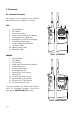
2 OPERATION 2.1 Location of Controls The location of the controls for the 150 and 200/250 are shown in Figures 2.1 and 2.
2.2 Operation – 150 Anti-clockwise The operation of any of the push buttons or the channel selector knob is confirmed by an audible beep from the unit. The operation of the controls for the 150 and 150 GMDSS is as follows: On/Off Button (1) Pressing this button will turn the radio on and off. To turn the radio off it is necessary to hold the button in for two seconds. This prevents the radio being accidentally switched off.
Backlighting On/Off (6) This button will illuminate the channel selection window for a period of ten seconds. The window will re-illuminate for a further ten seconds if a key is subsequently pressed, thus preserving battery life. Pressing this button again will switch the backlighting off. Channel Selection Knob (7) This is a sixteen-position rotary switch used to select the channels programmed into the radio.
2.3 Operation – 200/250 The operation of any of the push buttons, or the channel selector knob is confirmed by an audible beep from the unit. The operation of the controls for the 200, 250 and 250 GMDSS is as follows On/Off Button (1) Pressing this button will turn the radio on and off (Fig 2.6). To turn the radio off it is necessary to hold the button in for two seconds, preventing the radio being accidentally switched off.
D/W. While the radio is in Dual Watch mode, the D/W legend will be displayed on the LCD. REVERT Function - If D/W is pressed when CH16 is selected, the radio will revert to the previously selected channel. HI LO Squelch Up (8) This button will increase the receiver muting threshold (or SQUELCH) level, i.e a stronger signal will be required to activate the receiver. The squelch level selected is indicated by the bar chart on the LCD display (Fig 2.8).
NOTE - Second level functions are only available on scanning versions of the 200 and 250. On non-scanning versions, the F key is replaced with a backlighting key. D/W 16 SQ CH M+ SQ MS CH F AS - Backlighting (F-F) On scanning models of the 200 and 250, the LCD display backlighting can be switched on by pressing F and F again within two seconds. By keeping F depressed, the radio will step through the six levels of illumination available (Fig 2.10). A second press will turn the backlighting off.
MS - Memory Scan (F-Channel Up) This function operates in the same way as the Scanning function (F-Channel Down), except that it will only scan channels that have been entered into the Scan Memory. If no channels have been entered into the memory, then this function will not be available.
3 BATTERY USE SQ CH F AS The radio comes equipped with a 700- or 850mA-hour NiCad battery pack as standard (depending on model). All battery types are housed in an identical enclosure. Model Battery Pack Supplied 200 150 250 150 GMDSS 250 GMDSS NCB700 - 700mAh NCB850 - 850mAh NCB850 - 850mAh NCB850 - 850mAh NCB850 - 850mAh AXIS 200 3.1 Removal, Fitting and Options To remove the battery, lift the release lever situated at the base of the battery pack to the vertical position.
3.2 Charger Options The 200 is supplied as standard with a 12v drop-in trickle charger TCH12 that will accept the whole radio, or the battery alone (Fig 3.3). This charger will run from a standard 12v marine supply (12.6v–15.5v), or from 110v/ 220v/240v mains with an appropriate optional adapter/power supply. Charging with the trickle charger takes approximately 12–16 hours. There are also optional drop-in Commercial Trickle and Rapid chargers available (CTC1 and CRC1).
3.5 Notes on Charging 1. NiCad battery packs are supplied uncharged and need charging before use. 2. Charge the battery up to full charge when not in use, although it may lose a proportion of its charge after some months of storage. 3. Do not charge at temperatures below 0ºC or above 40ºC. 4. Check battery level indicator during switch on to determine remaining battery life. 5. Turn off if charging battery while fitted to Axis. 6.
3.8 Battery Life Guidelines To a large extent, the battery life will depend on the usage, or Duty Cycle of the radio – i.e the battery will be drained much quicker, if the radio is transmitting continually than if it is just receiving. Additionally, if the radio is set to High Power (5 Watts*), the power drain will be considerably greater than if transmitting on Low Power (1 Watt*).
4 ANTENNA & ACCESSORY SOCKET 4.1 Antenna The antenna for the radio is fitted to the unit via a robust screw fitting to an M8 threaded socket on the top of the radio (Fig 4.1). This system is more rugged than a traditional BNC connector, so the radio’s drop-proof integrity is not compromised by the antenna fixing.
5 APPENDIX 5.1 Spares & Accessories NCB700 The following spares and accessories are available from authorised Simrad Dealers. A list of dealers is included with this unit. Please quote the appropriate part number when ordering.
Carrying Accessories HS1 Handstrap BMT1 LC1 Bulkhead Mount Plate Leather Carrying Case BCP1 Leather Belt Clip c/w Adapter Plate ADP1 LYD1 Lanyard ADP1 Adapter Plate WB1 SS1 Shoulder Strap Aluminium Wall Mount Bracket (For use with TCH12) FLT1 Flotation Strap WPSM1:GY Waterproof Speaker Mike - Grey WPSM1:Y Waterproof Speaker Mike - Yellow 2.
5.2 Transmission Range Because VHF signals travel in a straight line and are not reflected back off the ionosphere as lower frequency signals are, the range of VHF signals is limited to ‘line of sight’, beyond which the other vessel passes behind the curve of the Earth. Therefore, the range will increase greatly the higher above sea level the antenna is, as Figure 5.1 illustrates (assuming maximum transmission power is used): Fig 5.
5.3 Frequency of Channels In the UK channels 0 and 00 will only be made available to Coastguard users with written authorisation.
5.4 Troubleshooting Symptom Possible Cause Remedy Unit will not switch on * Battery not charged * Battery not secured correctly in radio * Re-charge battery * Ensure battery is fully locked in (see section 3.1) Scan or Memory Scan is locking on a channel without a signal * Noise on the channel is holding the scan * Increase squelch level * Inhibit channel from scan - 200/250 (see section 2.
www.simrad.