
Instruction manual


Page 10
2 OPERATION
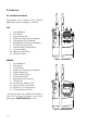
2.1 Location of Controls
The location of the controls for the 150 and
200/250 are shown in Figures 2.1 and 2.2:
150 –
1 On/Off Button
2 PTT Button
3(Accessory Socket)
4High/Low Transmit Power Button
5Autosquelch On/Off Button
6 Backlight On/Off (Channel Display)
7 Channel Selection Knob
8Audio Volume Control Knob
9 (Tx Status LED)
10 (Battery Status LED)
11 (Rx Status LED)
200/250 –
1 On/Off Button
2 PTT Button
3(LCD Screen)
4High/Low Transmit Power Button
5Audio Volume Up
6Audio Volume Down
7 Dual Watch (D/W)
8 Squelch Up/Enter Memory
9 Channel 16
10 Channel Up/Memory Scan
11 Squelch Down/Scan Inhibit
12 Function*/LCD Backlighting
13 Channel Down/All Scan
* Scanning models only. All functions listed in
italics are secondary functions accessed by
pressing the FUNCTION (F) key first.
AS
1
2
3
4
5
6
7
11 12 13
89
10
AS
1
2
3
7
8
91011
4
5
6
Fig 2.1 - 150 schematic
Fig 2.2 - 200/250 schematic