Broadband 3G™ Radar Broadband 4G™ Radar Installation Guide ENGLISH www.bandg.com www.simrad-yachting.com www.lowrance.
Contents 4 Welcome 4 4 4 5 What is Broadband radar? FMCW radar is different: How does FMCW radar work? Additional benefits of FMCW radar are: 6 Radar system overview 7 Installation 8 11 12 Considerations for direct roof mounting Connect interconnection cable to the scanner Connect the interconnection cable to radar interface box 14 Connect the Broadband radar to your display 14 15 15 16 16 Lowrance: HDS USA (no MARPA) Lowrance: HDS outside USA or with MARPA / chart overlay Simrad: NSS B&G: Zeus
Compliance The Broadband 3G™ and 4G™ Radars comply with the following regulations: • FCC Part 15. • Industry Canada RSS-Gen. • CE compliant with R&TTE directive. For further compliance information please refer to our websites: http://www.simrad-yachting.com/Products/Marine-Radars http://www.lowrance.com/Products/Marine http://www.bandg.
Disclaimer As Navico is continuously improving this product, we retain the right to make changes to the product at any time which may not be reflected in this version of the manual. Please contact your nearest distributor if you require any further assistance. It is the owner’s sole responsibility to install and use the instrument and transducers in a manner that will not cause accidents, personal injury or property damage. The user of this product is solely responsible for observing safe boating practices.
1 Welcome Congratulations on your purchase of the latest technology available in recreational marine radar.
FMCW = Frequency Modulated Continuous Wave The scanner transmits a ‘rising tone’ (Tx wave) with linearly increasing frequency. The wave propagates out from the transmitter retaining the frequency it had when it was transmitted. If it reflects off an object, it will return to the receiver, still at the frequency it had when originally transmitted. Meanwhile, the transmitter continues to output an increasing frequency.
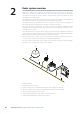
Radar system overview 2 The Broadband Radar is a state of the art navigation aid. It provides outstanding radar performance without the limitations of conventional pulse radars such as: dangerous high power microwaves, standby warm up time, 30 m blind spot (mainbang), high power consumption and large open arrays (which is what would be required to obtain the same image quality at shorter ranges).
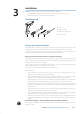
3 Installation Note: Follow these instructions carefully. Don’t take any shortcuts! • The Broadband Radar is factory sealed. It is not necessary to remove the cover. • Removing the cover will void the factory warranty. Tools Required 1. Drill 2. Torque wrench 3. Drill bit 9.5 mm (3/8”) 4. Screw driver 1 2 3 4 Choose the scanner location The radar’s ability to detect targets greatly depends on the position of its scanner.
Broadband Radar Compass TX 12.5 12.5 0.7 m (2.3 ft) Min Pulse Radar STBY Minimum distance to install near the ships compass is 0.7 m (3.3 ft). Do not install the Broadband Radar on the same beam plane as a conventional pulse radar. A pulse radar must be set to STBY or OFF any time the Broadband Radar is being operated. If possible ensure that the location site provides the scanner with a clear view all round the vessel.
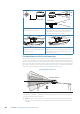
Better performance Broadband Radar Above illustrates that raising the Broadband scanner off the hard top allowing most of the radar energy to clear the hard top. Best performance Broadband Radar 850 mm Hard Top Width For best performance, the radar should be positioned to allow the beams to clear the superstructure of the boat. Below is a guide to determine scanner height in relation to a vessels hard top overall width. Optimum Performance 1.0 m 25° 1.2 m 1.4 m 1.6 m 1.8 m 2.0 m 2.2 m 2.4 m 2.
Mounting the scanner Use the supplied mounting template and tape it securely to the chosen location. Before drilling, check that: • you have oriented the mounting template correctly so that the front of the scanner unit will face the front of the vessel • the thickness of chosen location is not more than 18 mm (0.7”) thick. If the location is thicker, longer bolts than those supplied will be required • the four bolts supplied are M8 x 30 mm.
Connect interconnection cable to the scanner The scanner interconnection cable connects the scanner to the RI10 interface box (or Lowrance HDS via and ethernet adapter cable - 3G U.S only). The cable connects to the scanner using a 14 pin connector. • Protect the connectors when pulling cable through the boat and avoid putting strain on to the connectors • The interconnection cable is 9 mm in diameter.
Connect the interconnection cable to radar interface box To connect interconnection cable to Lowrance HDS (USA only) (see “Lowrance: HDS USA (no MARPA)” on page 14) A D F B E G C Data H Shield Black Yellow Red 1. Slide (F), (E) and (D) past the RJ45 connector 2. Connect data wires to the green terminal and power wires of the scanner interconnection block (phoenix connector) cable (G) 3. Connect RJ45 and phoenix connector to the radar interface box A H E D D 4.
Shortening the cable It is not recommended to shorten the cable, but if it is unavoidable, use the pin-out below to re-terminate the cable with a new RJ45 plug.
4 Connect the Broadband radar to your display Lowrance HDS USA (no MARPA) 3 1 NEP-2 (Optional) 2 2 4 FUSE FUSE _ + 1. Lowrance HDS 2. Ethernet adapter cable. 5 pin yellow male to RJ45 female 1.8 ft (6ft). Included in 3G™ kit 00010418-001 (Lowrance USA only). Can connect directly to the HDS, or via a NEP-2 Ethernet switch, or using a free Ethernet port on a LSS-1 Structure Scan module (if applicable) Note: Make sure this connection is made in a dry environment and is secured properly 3.
Lowrance HDS outside USA or with MARPA / chart overlay Simrad NSS (NMEA2000 network) The 3G and 4G radar connects to the Lowrance HDS and Simrad NSS in the same manner 2 HDS 1 3 Lowrance HDS or Simrad NSS NMEA2000 NSS Ethernet Power 4 5 FUSE NMEA2000 Ethernet 6 7 8 FUSE FUSE 9 9 _ + 10 NMEA2000 Network 1. 2. 3. 4. 5. 6. 7. 8. 9. Parts required for chart overlay / MARPA Lowrance HDS or Simrad NSS Broadband 3G™ or 4G™ Radar Interconnection cable (Lowrance 10 m (33 ft) Simrad 20 m (65.
B&G Zeus Simrad NSO, NSE and NSS (SimNet network) 2 1 Zeus B&G Zeus SIMRAD NSO, NSE or NSS MFD 3 SimNet Ethernet Ethernet SimNet 4 5 6 FUSE 7 FUSE NSO 8 10 97 Parts required for Chart overlay / MARPA FUSE 12 _ + SimNet Ethernet Alternative: NMEA0183 heading NMEA2000 cables SimNet cables Ethernet cable Ethernet cables if using NEP-2 Ethernet SimNet NSE NSS SimNet Network 1. 2. 3. 4. 5. 6. 7.
5 RI10 Connections 1 5 2 3 4 1. Connects the RI10 to a SimNet or NMEA2000 network to allow heading and position infor2. 3. 4. 5. mation to be sent to the scanner for MARPA calculations Main data network interface between the radar and the display (ethernet) Provides data and power connection between the Broadband radar dome and the RI10. Power cable (see “Connect power” on page 18) Green LED indicates power is supplied to the RI10 and indicates SimNet state.
Connect power 6 The Broadband Radar can operate on 12 or 24 V DC systems. The Broadband Radar requires +V DC to be applied on the yellow power on wire in order to operate. This can be achieved in one of three ways: 1. Common the red and yellow wire together, and connect to a fused switch. Radar will power on in standby when power is applied. When switch is off, radar will draw no power 2. Use ignition or install a switch that will provide power to the yellow wire.
7 Setup and Configuration Setup and configuration of the Broadband radar has been simplified compared to traditional pulse radars. There is no zero range adjustment (time delay), no warm up time, and no burn in required. The following sections cover the available adjustments. Note that the menu examples used are from the Simrad NSE. While these differ aesthetically from the Lowrance interface, the content is essentially the same.
Adjust bearing alignment... Adjust the heading marker. This is to align with the heading marker on the screen with the center line of the vessel, this will compensate for any slight misalignment of the scanner during installation. Any inaccuracy will be evident when using MARPA or chart overlay. Point the boat to the end of a head land or peninsula. Adjust the bearing alignment so the heading line touches the end of the same head land or peninsula. Adjust local interference reject...
To start the radar: From the radar screen select the Transmit button. RI10 heading source selection: The RI10 receives heading via SimNet or NMEA2000 network and transmits this data to the radar, where MARPA processing is performed. For Simrad installations with more than one SimNet heading source the RI10 will use the Simrad group source. The source used by the Simrad group can be viewed or changed via an NSE / NSO / NSS display in the Settings>Network>Sources… menu.
6. The radar source selection is not global, so will only apply to the display on which the source was selected. The radar source will need to be setup for each display on the network. Once the radar sources have been set up they will be retained for every system power-up until changed by the user Dual Range setup (Broadband 4GTM Radar only): With a Simrad NSE display connected to a Broadband 4G™ radar, it’s possible to run the radar in dual range mode.
8 Maintenance Clean the radome using soapy water and a soft cloth. Avoid using abrasive cleaning products. Do not use solvents such as gasoline, acetone, M.E.K etc. as this will damage the dome surface. After years of use the drive belt may have to be replaced. The transmitter in the Broadband Radar is solid state and will not require regular replacement, unlike the magnetron found in conventional pulse radar.
Scanner 280 mm (11.02”) 9 Dimension Drawings 489.6 mm (19.28”) 488.6 mm (19.24”) FRONT 232.5 mm (9.15”) D B A 233.0 mm (9.17”) 128.3 mm (5.05”) 24 | Key Description A B C D Cable entry area Cable retention channel Bolt holes x 4 M8 x 30 mm Breather Dimension Drawings | Broadband 3G/4G™ Radar Installation Guide 128.3 mm (5.05”) 114.6 mm (4.51”) 141.5 mm (5.
Radar interface box 171 mm (6.76") 92 mm (3.63") 25 MM (1") 154 mm (6.
10 Specifications Broadband 3G™ Radar Characteristic Technical Data Compliance CE, FCC (ID: RAY3G4G), IC: 4697A-3G4G Environmental IEC60945 : 2002 Operating Temperature: -25° to +55°C (-13° to +130°F) Relative humidity: +35° C (95° F), 95% RH Waterproof: IPX6 Relative wind velocity Power consumption (with 10m cable) 51 m/sec (Max:100 Knots) Operating: 18W (Typ.) @ 13.8Vdc Standby: 2W (Typ.) @ 13.8Vdc ~ 150mA DC input (at end of radar cable) 9V to 31.2Vdc (12/24 Volt systems).
Broadband 4G™ Radar Characteristic Technical Data Compliance CE, FCC (ID: RAY3G4G), IC: 4697A-3G4G Environmental IEC60945 : 2002 Operating Temperature: -25° to +55°C (-13° to +130°F) Relative humidity: +35° C (95° F), 95% RH Waterproof: IPX6 Relative wind velocity 51 m/sec (Max:100 Knots) Power consumption (with 10m cable) Operating: 20W (Typ.) @ 13.8Vdc (21W in dual range mode) Standby: 2.9W (Typ.) @ 13.8Vdc ~ 170mA DC input (at end of radar cable) 9V to 31.2Vdc (12/24 Volt systems).
Navico Broadband radar part numbers Broadband radar scanner part numbers Model Part Number Description Length Scanner 3G™ 4G™ 000-10416-001 Broadband 3G™ Radar 000-10417-001 Broadband 4G™ Radar RI10 RI11 AA010189 AA010204 Broadband radar SimNet interface box Broadband radar serial interface box AA010211 Broadband scanner interconnection cable 10 m (33 ft) AA010212 AA010213 Broadband scanner interconnection cable Broadband scanner interconnection cable 20 m (65.6 ft) 30 m (98.
11 RF exposure compliance certificate RF exposure compliance certificate | Broadband 3G/4G™ Radar Installation Guide | 29
30 | RF exposure compliance certificate | Broadband 3G/4G™ Radar Installation Guide
RF exposure compliance certificate | Broadband 3G/4G™ Radar Installation Guide | 31
*988-10113-003* www.bandg.com www.simrad-yachting.com www.lowrance.