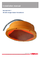
Installation manual Simrad 38-7 38 kHz single beam transducer www.simrad.
Simrad 38-7 Installation manual This document provides a general description of how to install the Simrad 38-7 Single beam transducer. The information must be regarded as general guidelines and recommendations only. The installation shipyard must design and manufacture installation hardware to fit the 38-7 transducer on each individual vessel. 130003/D 16.11.
Document history Simrad document number: 130003 / ISBN-13: 978-82-8066-111-1 / Current revision: D Rev.A — First version. Common for transducers 38–7 and ES38B. Rev.B 01.09.1991 Updated. Common for transducers 38–7 and ES38B. Rev.C 02.10.2009 Improved. Valid only for Simrad 38–7. Rev.D 16.11.2009 Support bar description changed, must be installed. Added drawing Support bar [206574] on page 39.
Installation manual Table of contents ABOUT THIS MANUAL ....................................................... 5 SIMRAD 38-7 .................................................................... 6 WHERE TO MOUNT THE TRANSDUCER ............................... 7 HOW TO INSTALL THE TRANSDUCER .............................. 11 Transducer installation in blister ............................................................................ 11 Use the mounting ring .................................................
Simrad 38-7 Introduction to Emuge self-locking threads................................................... 25 Drawing standard........................................................................................ 26 Taps and gauges.......................................................................................... 26 Self-lock taps provided by Simrad ............................................................... 27 Supplier and manufacturer...........................................................
About this manual ABOUT THIS MANUAL Purpose The purpose of this installation manual is to provide the generic descriptions and illustrations that allows you to understand the basic principles for echo sounder transducer installation. About the information provided in this document The information in this document must be regarded as general guidelines and recommendations only. The installation shipyard must design and manufacture installation hardware to fit each individual transducer and vessel.
Simrad 38-7 SIMRAD 38-7 The purpose of this manual is the provide the basic information required to install the Simrad 38-7 Single beam transducer.
Where to mount the transducer WHERE TO MOUNT THE TRANSDUCER A single answer to the question where to locate the transducer cannot be given. It depends very much on the vessel’s construction, how the hull is shaped and how the water runs along the hull. There are however a number of important guide lines, and some of these are even conflicting. Mount the transducer deep Mount the transducer at a deep position on the hull.
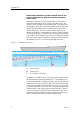
Simrad 38-7 Mount the transducer at the forward part of the hull to minimise the effects from the boundary water layer When the vessel forces its way through the sea, the friction between the hull and the water creates a boundary layer. The thickness of the boundary layer depends upon vessel speed and the roughness of the hull. Objects protruding from the hull, and dents in the hull, disturb the flow and increase the thickness of the boundary layer.
Where to mount the transducer Mount the transducer far away from the propellers The propulsion propeller is the dominant noise source on most fishing vessels, research vessels, merchant vessels and pleasure crafts. The noise is transmitted through the sea water. For this reason, the transducer should be placed far away from the propeller, which means on the fore part of the hull. Positions outside the direct line of sight from the propeller are favourable.
Simrad 38-7 Summary and general recommendations Some of the above guide lines are conflicting, and each case has to be treated individually in order to find the best compromise. Generally the propeller noise is the dominant factor, and a recommended transducer location is in the fore part of the hull, with maximum distance from the bow equal to one third of the total length of the hull at the water line.
How to install the transducer HOW TO INSTALL THE TRANSDUCER There are many different ways to mount the transducer. These are the recommended methods to mount a streamlined and circular transducers under the hull or in a towed body. Transducer installation in blister With a transducer with circular housing, one recommended installation method is by using a blister. The transducer blister must be designed and manufactured by the installation shipyard to fit the vessel’s size and hull shape.
Simrad 38-7 Example: Large circular transducer The illustration below shows a typical transducer blister designed for a large transducer. Note that due to the physical size of the transducer, a U-shaped support bar (E) is used to support the transducer. The purpose of this support is to prevent the transducer from being pushed up into the blister in heavy seas.
How to install the transducer The interior of the blister must be filled with sea water. Use drainage holes in the bottom and an air outlet on the top. The water pressure behind the transducer will then compensate for the outside pressure during vessel movements in rough sea. We recommend that large diameter transducers are fitted with a horizontal U-shaped support bar. This bar can then be secured to the mounting ring using threaded rods. The transducer cable penetrates the hull in a stuffing tube.
Simrad 38-7 Observe the horizontal and vertical distances (C and D) between the keel and the transducer blister. On a medium sized vessel, the horizontal distance (C) should be approximately 1 meter. The vertical distance (D) must in general be as small as possible. This is important to prevent the keel from shadowing the transducer beam in shallow waters.
How to install the transducer mount it, the hull plating and the putty around the transducer is as even and smooth as possible. Obstructions on these surfaces will create problems with turbulent flow. Use a horizontal support bar on large transducers Due to its physical size, the 38-7 transducer must be fitted with a horizontal support bar. The purpose of this support bar is to protect the transducer from damage in the event of slamming.
Simrad 38-7 The standard procedure for flush mounting on a steel vessel is to weld a steel tank inside the hull, and mount the transducer into this tank. Use the mounting ring Large circular transducers are designed to be mounted using a mounting ring. A suitable mounting can be provided by Simrad, drawings are also available for local production. The mounting ring is welded to the hole prepared for the transducer.
How to install the transducer Example: Flush mounting in a steel tank Transducer mounting in a steel tank is shown in the figure below. Figure 7 Flush mounting in a steel tank A Steel tank B Water C Drainage hole D Cable service loop E Steel tube for air outlet F Stuffing tube G Cable in steel conduit G E F A B D (CD17012A) C Transducer with acoustic window Vessels operating in arctic waters need special attention on transducer installation.
Simrad 38-7 Example: Acoustic window The transducer shown in the figure below is mounted inside the tank behind a strong acoustic window which could be made of polycarbonate. The tank is filled with oil. Figure 8 Acoustic window F A Steel tank B Oil C Acoustic window D Cable service loop E Stuffing tube F Cable in steel conduit G Oil inlet G E A D B (CD017012B) C Transducer mounted inside the hull The transducer can also be mounted inside the hull.
How to install the transducer Use the mounting ring Large circular transducers are designed to be mounted using a mounting ring. A suitable mounting can be provided by Simrad, drawings are also available for local production. The mounting ring is welded to the hole prepared for the transducer. Bolts through the transducer body into the mounting ring will secure the transducer in place. Note that several transducers use direction guides to allow correct mounting.
Simrad 38-7 Transducer mounted on a drop keel The use of a drop keel with the purpose of stabilising the vessel is well known. A drop keel is also a superior platform for echo sounder transducers. Such instrument keels have been built, mainly on research vessels, often protruding as far as three meters below the hull. At that depth, the water is free of air bubbles up to very high sea states. The vessel is then able to perform reliable acoustic measurements in open sea a larger part of the year.
How to install the transducer Retractable transducer Hull units allowing the transducer to be lowered and hoisted are commonly used for horizontal looking sonars. When not in use, the transducer is retracted into a trunk. The retractable hull unit is more expensive than a blister, but on vessels with a hull where it is difficult or impossible to install a blister, it may still be worth while. The principles of a hull unit with a retractable transducer is shown below.
Simrad 38-7 STEEL CONDUIT Why use steel conduits? It is strongly recommended to lay a steel conduit from the transducer’s cable gland to the echo sounder transceiver, and to pull the transducer cable through this conduit. There are several reasons for this. • It will make it easier at a later stage to replace the transducer. • Noise and interference from other electrical equipment is greatly reduced. • The risk of flooding is greatly reduced if the pipe is terminate above the water line.
Transducer handling and maintenance TRANSDUCER HANDLING AND MAINTENANCE You MUST observe the following rules for handling, maintenance and painting. Rules for transducer handling Note Do not lift the transducer by the cable. Do not expose the transducer to direct sunlight. Do not expose the transducer to excessive heat. Transport protection Some transducers are delivered with a cover plate on the face for protection during transport.
Simrad 38-7 Approved anti-fouling paints This is Simrad’s list of approved antifouling paints on polyurethane transducer housing. Jotun Head office address: P.O.Box 2021, N-3248 Sandefjord, Norway Website: www.jotun.com. 1 Racing 2 Non-stop 3 Safeguard Universal primer (125 micron) with Antifouling SeaQuantum Ultra (125 micron) 4 Antifouling Seaguardian International Marine Coatings Address: World-wide offices Website: www.international-marine.com.
Transducer handling and maintenance Introduction to Emuge self-locking threads Emuge self-lock is a tap design with an integrated locking feature. Standard metric bolts are used. The internal thread provides a self-locking connection, which can be used repeatedly. It is not necessary to involve a secondary locking device (e.g. chemical, nylon or mechanical). The Emuge self-lock bolts withstand vibrations better than standard (metric) threads, because the thread contact stops the sideways movement.
Simrad 38-7 • Economically efficient locking system, no additional components are necessary • Undiminished holding power even under dynamic stress • Repeated loosening and re-tightening without loss of function • Internal threads can be produced with Emuge taps, cold forming taps or thread mills • Larger thread hole diameters, i.e.
Transducer handling and maintenance Figure 12 Example of use (CD017020C) Note In the case of tapping through holes it is important that the profile of the Emuge self-lock threads is in the correct direction compared with the entering direction of the bolt. Use Emuge self-lock gauges. Note that the gauge must be used in the correct direction. Self-lock taps provided by Simrad The following self-lock taps are on stock at Simrad, and can be ordered from us. Threads Drill diameter for threads Part.
Simrad 38-7 TRANSDUCER CABLE SPLICING If you need to cut or lengthen the transducer cable, you must splice it correctly. The cable between the junction box and the transceiver must then be supplied by Simrad, and this must be the same type as used on the transducer(s). To splice the cable, use a metal junction box with EMC cable glands and a terminal block. The terminal block must provide solid fastening of the cable ends as well as sufficient insulation between the wires.
Drawing file DRAWING FILE This chapter contains relevant drawings related to the electrical and physical installation of the Simrad 38-7 Single beam transducer. Note The mechanical drawings are for information and guidance only. They are not in scale, and may differ slightly from the original drawings. All dimensions are in mm unless otherwise is noted. The original installation drawings are available on PDF and/or DWG (AutoCad) format. Visit www.simrad.com to download.
Simrad 38-7 General Purpose Transceiver (GPT) wiring Observe the drawings below to connect the Simrad 38-7 Single beam transducer to the General Purpose Transceiver (GPT). For more information about these connections, refer to the applicable echo sounder installation manual. B A M C L D K E Transducer cable GPT Transducer socket N F H J Junction Box (1:1) (Optional) D C Drain wire Screen W802-1 Rev.
Drawing file General Purpose Transceiver (GPT) transducer plug assembly Upper plug case Plug fastening ring Contact body Retaining ring Outer screen and inner screen braid wire untaped and spread out under washer Outer screen together with inner screen. Drain wire, fold back over jacket and temporary fastened with tape. Heat-shrinkable tubing Lower plug case Washers Bottom cap and cable clamp Rubber sleeve Rubber sleeve Note: All measurements are in mm. The drawing is not in scale.
Simrad 38-7 Outline dimensions and installation drawings Note When you fasten the transducer to the mounting ring, apply Loctite 270 on each bolt, and tighten the bolts several times. Use maximum torque 32 Nm. In addition to the drawings available in this chapter, additional drawings are provided on our web site. See www.simrad.com.
Drawing file Outline dimensions [074647] 45° SIMRAD FOR WARD ø450 ø424 150 Standard cable length: 20 meters ø11 37 12 ø22 ø480 All measurements in mm. The drawing is not in scale 130003/D 830-074647 Rev .
Simrad 38-7 Mounting ring [074076] 60 ±0.2 30 ±0.2 ø11 ø20 Countersunk 17 ±5 790 Note 1 A B 446 ±0.2 B M10 Self-lock threads (8 holes) 45° F Marked on plate with steel types 223 ±0.2 A 560 ±1 Note 1 Note 1: For keel installation, size of plate should be adapted to keel design. Surface treatment: 1) Sand blasted after grinding to SA.2.5 2) One coat of red ferric oxide primer All measurements in mm. The drawing is not in scale 34 499-074076 Rev .
Drawing file 72 +0.5/-0 12 Section B-B 6.3 R3 2 x 45° 6.3 ø11 ø20 6.3 6.3 30 20 17 37 +0/-0.5 3.2 ø427 +1/-0 ø450 ±0.5 ø483 +0/-1 ø488 +0/-1 ø510 ±1 6.3 Ring S355J0 (St.52) ø520x420x75 Plate S355J0 (St.52) 12x570x800 All measurements in mm. The drawing is not in scale 130003/D Section A-A 499-074076 Rev .
Simrad 38-7 Recommended arrangement [074544] Air outlet Self-locking threads Steel blister , to be made by shipyard Refer to drawing 1 11-074077 FOR WARD Steel plate with mounting ring can be supplied by Simrad Refer to drawing 499-074076 Ceramic transducer SIMRAD FOR WARD Washer Bolt M10 Apply Loctite 270 on each bolt. Use torque 32 Nm. All measurements in mm. The drawing is not in scale 36 Tighten each bolt several times. 820-074544 Rev .
Drawing file Recommended transducer location Approx 3 deg Minimum 400 mm Approx 1 m Air/water outlet (optional) near the echo sounder , above water level Important: In case of slamming in rough sea, use support beam 099-206575. ø35 Anti-fouling paint: The transducer face is made of polyurethane. In general, due to the risk of chemical reaction, it must not painted. If fouling is a problem, observe the recommended antifouling paints listed in the transducer installation manual and on www.simrad.com.
Simrad 38-7 Mounting procedure [088759] Protective plate: 519-088758 (12 and 18 kHz transducers) 519-074659 (38 kHz transducers) 1) Remove nuts and washers before mounting the transducer in the steel blister . 2) Jack up the transducer into the steel blister . fasten the transducer with four mounting screws. 3) Remove the protecting plate. All measurements in mm. The drawing is not in scale 38 820-088759 Rev .
Drawing file Support bar [206574] Socket head cap screw Class 80 M10x120 A4-80-MC6S (560-078780) Support bar (*) (579-206572) Clamp (579-206570) A A Mounting ring (499-074076) Elastic compound Transducer body (*) On the Autocad drawing, this item is referred to as "Supporting Channel" A- A Clamp (579-206570) 1) Use a drill, or similar tool, to open the bolt holes in the transducer flange. The holes are partly filled up with polyurethane moulding compound.
Simrad 38-7 ø10 holes for hex. wrench Transducer with wooden protective plate All measurements in mm. The drawing is not in scale 40 820-206574 Rev .
Index Index A About, 5 information in this manual, 5 Acoustic window, 23 example, 18 installation, 17 Additional information, 5 Air outlet example, 12 Anti-fouling paint, 24 Approval maritime authorities, 5 Arrangement drawing, 36 B Blister Common guidelines, 12 installation, 11 physical location, 13 Boundary water layer, 8 Bow thrusters noise, 9 Box keel example, 15 installation, 14 C Cable transducer, splicing, 28 Clamping ring blister, 11 drawing, 38 example, 12 Clamping rings, 11, 14, 16–17, 19 Clean
Simrad 38-7 O Order number transducer, 6 Outline dimensions drawing, 33 P Paint anti-fouling, 24 Painting transducer face, 23 Physical dimensions drawing, 33 Physical location blister, 13 Propeller noise, 9 Protruding objects, 7 Purpose this manual, 5 R Termination GPT, 30 Toe-in, 13 Transducer lifting, 23 order number, 6 recommended location, 10 Transducer cable splicing, 28–29 termination, 30 Transducer face cleaning, 23 painting, 23 Transducer plug drawing, 31 Transport protection, 23 W Water filled
Index 130003/D 43
Simrad document number: 130003 / Version D ISBN-13: 978-82-8066-111-1 ©2009 Kongsberg Maritime AS S im r a d Ko n g s b e r g M a r it im e A S S t ra n d p rom e n a d e n 5 0 P. O. Bo x 1 1 1 N- 3 1 9 1 H o r t e n , N o r w a y Te le p h o n e : + 4 7 3 3 0 3 4 0 0 0 Te le fa x : + 4 7 3 3 0 4 2 9 8 7 w w w . s im r a d . c o m c o n t a c t @ s im r a d .