Instruction manual Simrad DR76, AR78, AR80, AR81 and AR83 Digital, Analog and Bearing Repeaters English www.simrad-yachting.
INSTRUCTION MANUAL Instruction manual DR76 Digital repeater, AR78/AR80 Analog repeaters and AR81/AR83 Bearing repeaters This manual is used for installing and operating Simrad’s Digital -, Analog- and Bearing Repeaters.
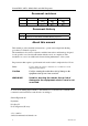
Simrad DR76, AR78, AR80, AR81 and AR83 Repeaters Document revisions Rev Date A 11.11.03 B 02.09.04 Written by Checked by Approved by Document history Rev. A First issue Rev. B Updated to include AR81 and AR83 Bearing repeaters. About this manual This manual provides installation instructions, operation and simple fault finding procedures for Simrad’s repeaters.
INSTRUCTION MANUAL Table of contents 1 INTRODUCTION ................................................................1 2 DR76 DIGITAL REPEATER .................................................2 2.1 Technical specifications .................................................................................2 2.2 Installation ......................................................................................................3 Panel mounting ................................................................
Simrad DR76, AR78, AR80, AR81 and AR83 Repeaters 5 SPARE PART LIST............................................................25 6 DRAWINGS .....................................................................
INSTRUCTION MANUAL 1 INTRODUCTION The DR76 Digital Repeater, the AR78/AR80 Analog repeaters, and AR81/AR83 Bearing repeaters have been designed to accept a variety of digital inputs that are sensed when first switching on the repeater. The repeaters accept serial data (RS422). The D-type connector has pins allocated for power and serial data. The serial input is configured to recognize NMEA 0183 HDT, HDG and HDM sentence structures in priority order.
Simrad DR76, AR78, AR80, AR81 and AR83 Repeaters 2 DR76 DIGITAL REPEATER 2.1 Technical specifications Dimensions ............................................................. Refer page 28 Weight (nominal):................................................................1.2 kg Mounting options:.................................Panel or bracket (Option) Finish: .......................... Light Weather-work Grey (BS3816-676) Construction:............................................
INSTRUCTION MANUAL 2.
Simrad DR76, AR78, AR80, AR81 and AR83 Repeaters Optional bracket mounting Numbers in brackets refer to the drawing below.
INSTRUCTION MANUAL 2.3 Cable connection Caution Any voltage supplies other than those specified in the product specification, page 2, may cause damage to the repeater. The repeaters have no power switch, and the repeater will be automatically started when the cable is connected to the unit. It is therefore recommended to connect the cable via an external power switch. The repeaters are designed to run on 24VDC, and accept a digital RS422 data signal. The repeater is supplied with a 2.
Simrad DR76, AR78, AR80, AR81 and AR83 Repeaters 2.4 Operation TURN INDICATOR TRUE DIM BAR DIM SET DIGIT HEADING SIMRAD DR76 The DR76 front panel includes the following elements: • Horizontal Turn indicator TURN INDICATOR - used either as a rate of turn indicator, or as a steering indicator to indicate the difference between actual and set course TRUE • Heading display - showing the input heading received from the transmitting device, e.g.
INSTRUCTION MANUAL If the signal is invalid or missing after 1 second, this will be indicated with flashing heading display. When the defined input signal is lost, power must be switched off and on again. If the cable not is connected via an external switch, the cable must be disconnecting and reconnected again to define a new input signal. Adjusting display illumination The display illumination on both displays may be adjusted by using the dimmer buttons.
Simrad DR76, AR78, AR80, AR81 and AR83 Repeaters Setting the Display mode DIM BAR SET Active mode is selected by pressing the SET button and the DIM BAR button simultaneously. The last digit in the heading display will now cycle between the three display modes. Then selected mode is indicated, this mode is activated by releasing both buttons. 2.
INSTRUCTION MANUAL 3 AR78/80 ANALOG REPEATERS 3.1 Technical specifications Dimensions: ................................................ Refer page 29 and 30 Weight (nominal): AR78:................................................................2.9 kg AR80 .................................................................1.9 kg Mounting: .............................................Panel or bracket (Option) Finish: ..................................................... Satin black (RAL 9005) Construction:...
Simrad DR76, AR78, AR80, AR81 and AR83 Repeaters 3.2 Installation Panel mounting Note 1 Drill the mounting holes and make a panel cut-out according to supplied drilling template 2 Use the supplied screws to fasten the control unit to the panel Do not over- tighten the mounting screws! 3 Apply the front panel corners Refer the drawing on page 3 showing the panel mounting for DR76. Optional bracket mounting Numbers in brackets refer to the drawing below.
INSTRUCTION MANUAL 3.3 Cable connection Caution Any voltage supplies other than those specified in the product specification, page 9, may cause damage to the repeater. The repeaters have no power switch, and the repeater will be automatically started when the cable is connected to the unit. It is therefore recommended to connect the cable via an external power switch. The repeaters are designed to run on 24VDC, and accept a digital RS422 data signal. The repeater is supplied with a 2.
Simrad DR76, AR78, AR80, AR81 and AR83 Repeaters 3.4 Operation DIM SIMRAD AR 80 The analog repeaters include a rotating dial and a dimmer button. Turning the repeater ON The repeaters have no separate power button, and the unit is automatically turned on when the cable is connected to the unit. The repeaters have been designed to accept a variety of NMEA input sentences. When the cable is connected to the repeater, it will automatically sense which sentence that is present.
INSTRUCTION MANUAL 3.5 Commissioning Perform the following tests when commissioning the repeater: 7 Ensure that the mechanical installation and cable connection has been completed according to the description on previous pages 8 Connect the cable to the repeater. The repeater will automatically sense which digital signal that is present - The repeater will align itself to zero and then to the transmitted gyro heading 9 3.6 Ensure that the lighting is set to a suitable level.
Simrad DR76, AR78, AR80, AR81 and AR83 Repeaters 4 AR81/83 BEARING REPEATERS 4.1 Technical specifications Dimensions: ............................................................ Refer page 31 Weight (nominal):................................................................4.5 kg Mounting: ...........................................Dedicated holders or stand Connections: ...................................................Via holder or stand Compass safe distance: ..........................................
INSTRUCTION MANUAL 4.2 Installation The AR81/AR83 bearing repeaters have to be mounted by using one of the repeater holders or in the repeater stand. Refer SPARE PART LIST, page 25. Refer dimensional drawings for repeater holders and repeater stand, page 32 onwards. 4.3 Cable connection and DIP switch settings Caution Any voltage supplies other than those specified in the product specification, page 14, may cause damage to the repeater. The AR81/AR83 repeaters are supplied with a 1.8 m cable.
Simrad DR76, AR78, AR80, AR81 and AR83 Repeaters 8 SWITCH DEFAULT S1-1 ON FUNCTION DESCRIPTION 1-1 OFF 1-2 OFF ON 20 msec (IEC-2) 1-3 OFF 1 1-1 ON S1 1-2 OFF S1-2 OFF 100 msec (IEC-1) 1-3 OFF Setup for receive format 1-1 OFF 1-2 ON 200 msec (IEC-1) 1-3 OFF 1-1 ON S1-3 OFF 1-2 ON 1 sec (IEC-1) 1-3 OFF 1-1 OFF 1-2 OFF TK format 1-3 ON 8 ON 1 S3 16 S1-4 OFF Not used S1-5 OFF Not used S1-6 OFF Repeater type S1-7 - Polarity for offset ON Software update OFF = Softwa
INSTRUCTION MANUAL Connecting an AR81/83 repeater to a GC80/85 Compact gyro system The AR81/83 should be connected to one of the four TX ports in the Compact control unit as shown on the figure below: GC80/85 COMPACT CONTROL UNIT REPEATER HOLDER / REPEATER STAND CONNECTION BOX TB1 1TX+ 1TX1TSC 1R241R24+ 2TX+ 2TX2TSC 2R242R24+ 3TX+ 3TX3TSC 3R243R24+ 4TX+ 4TX4TSC 4R244R24+ 29 30 31 32 33 34 35 36 37 38 39 40 41 42 43 44 45 46 47 48 * AR81/AR83 BEARING REPEATER 1.
Simrad DR76, AR78, AR80, AR81 and AR83 Repeaters ICIF board F3 F2 F4 F1 F5 F8 TB2 TB3 When an AR81/83 is connected to a GC80/85 Compact gyro system, the serial output signal from the gyro has to be set to IEC-61162-1 ed.2. This is done by setting a jumper on the ICIF board in the GC80/85 Compact Control unit.
INSTRUCTION MANUAL Connecting an AR81/83 repeater to a GC80/85 Expanded/Dual gyro system 10 TX channels are available when connecting the AR81/83 repeater to a GC80/85 Expanded or Dual gyro system.
Simrad DR76, AR78, AR80, AR81 and AR83 Repeaters When an AR81/83 is connected to a GC80/85 Expanded or Dual gyro system, the serial output signal from the gyro has to be set to IEC-61162-1 ed.2. This is done by setting a jumper on the SCC or SIFC board in the GC80/85 Expanded, or on the SCC or SCOIF board in the Dual control unit. Depending on which TX port that is used for connecting the repeater, the jumpers have to be set as described in the following pages.
INSTRUCTION MANUAL SIFC board J27 J26 J13 J12 J11 J10 J9 J8 J7 J6 J13 J12 J11 J10 J9 J8 J7 J6 Refer to the manual for your gyro system for more detailed information about the different jumper settings.
Simrad DR76, AR78, AR80, AR81 and AR83 Repeaters SCC board 2 J7 J8 6 5 2 4 1 3 2 1 6 5 2 4 1 3 J7 1 J8 SCOIF board J38 31 3 J39 1 3 J40 1 3 J41 1 J38 J24 6 5 1 2 4 2 4 2 4 2 4 2 J22 31 J41 31 J43 31 J42 13 4 2 4 2 4 2 4 2 J35 J34 J29 J30 J26 J23 J25 J39 J40 J41 2 4 2 4 2 4 2 1 3 1 3 1 3 2 4 2 4 2 4 1 3 1 3 1 3 12 1 2 12 1 2 4 12 34 1 3 2 1 S1 J20 24 13 24 J18 2 1 2 J43 24 13 24 J42 24 13 24 J45 24 13 24 J44 24 13 J37 24 13 1 3 1 1 3 1 3 1 3 J36 J28 J33 J32 J31 J27
INSTRUCTION MANUAL 4.4 Operation Turning the repeater ON The repeater holders and the repeater stand have a power button on the connection box. When the cables are connected and the jumper set in the control unit according to the previous pages, the repeater is turned on by switching the power button. If the signal is invalid or missing after 1 second, the repeater will indicate this by rotating the dial back and forth +/-35° around the last known heading.
Simrad DR76, AR78, AR80, AR81 and AR83 Repeaters 4.6 Fault finding The AR81/83 are sealed units, and breakage of the security seal will invalidate the warranty. If trouble is encountered, make preliminary checks as described below. If the problems remain unsolved, contact your nearest Simrad dealer for assistance. Symptom Probable fault Remedy The repeater does not operate. No power or incorrect power connection. Check incoming power supply.
INSTRUCTION MANUAL 5 SPARE PART LIST The following tables list part numbers for all standard and optional equipment that may be delivered for DR76, AR78, AR80, AR81 and AR83 repeaters. Part no Description 27103365 DR76 Digital repeater 27103340 AR78 Analog repeater 27103324 AR80 Analog repeater 27101732 Single scale Bearing Repeater NMEA. To be mounted in BB holder, MB Holder or BH stand. IMO A424 27101740 Dual scale Bearing Repeater NMEA. To be mounted in BB holder, MB Holder or BH stand.
Simrad DR76, AR78, AR80, AR81 and AR83 Repeaters Part no Description 27103571 AR80 Mounting bracket 27102870 AR81/AR83 Repeater Holder Gimballed bracket for indoor mounting of bearing repeater 27103076 AR81/AR83 Repeater Holder. Trunnion bracket for bearing repeater 27102862 AR81/AR83 Repeater Stand Binnacle for outdoor mounting of bearing repeater. 27102888 AR81/AR83 Azimuth Circle Used on bearing repeater to take bearings on celestial bodies and surface targets etc.
INSTRUCTION MANUAL 6 DRAWINGS The following drawings are enclosed: Drawing name Note 20221487 / B Drawing no. Rev. DR76 Digital repeater. Dimensions D2-710354 A AR78 Analog repeater. Dimensions D2-710355 A AR80 Analog repeater. Dimensions D2-710356 A AR81/AR83 Bearing repeater. Dimensions N4-710302 A AR81/AR83 Repeater holder (BB). Dimensions N4-710303 - AR81/AR83 Repeater holder (BH) Dimensions N4-710304 - Repeater stand (BH).
Simrad DR76, AR78, AR80, AR81 and AR83 Repeaters 28 20221487 / B
INSTRUCTION MANUAL 20221487 / B 29
Simrad DR76, AR78, AR80, AR81 and AR83 Repeaters 30 20221487 / B
INSTRUCTION MANUAL 20221487 / B 31
Simrad DR76, AR78, AR80, AR81 and AR83 Repeaters 32 20221487 / B
INSTRUCTION MANUAL 20221487 / B 33
Simrad DR76, AR78, AR80, AR81 and AR83 Repeaters Simrad Robertson AS EGERSUND NORWAY BH Repeater Stand Dimensions 1 34 1 N4 - 710308 20221487 / B
DR76, AR78, AR80, AR81 and AR83 Repeaters Manual EN, Doc.no.20221487, Rev.