Operator manual Simrad AP24 Autopilot English www.simrad-yachting.com Sw.1.
Operator manual Simrad AP24 Autopilot English Sw.1.3 Document no: 20222535 Revision: C Date: January 2010 The original language for this document is English. In the event of any discrepancy between translated versions and the English version of this document, the English document will be the official version. To the best of our knowledge, the content in this publication was correct at the time of printing.
About this manual Rev. A 06.11.07 First issue Rev. B 25.03.08 Rev. C 06.01.10 Updated according to autopilot software 1.2. Updated according to autopilot software 1.3. This manual is intended as a reference guide for operating and maintaining the Simrad AP24 autopilot. An autopilot is a complex control system so please take time to read this manual to get a thorough understanding of the operation, the system components and their relationship to a complete AP24 autopilot system.
Contents 1 Operation.................................................... 5 1.1 Overview ................................................5 1.2 ON/OFF ..................................................8 1.3 Backlighting ............................................9 1.4 Standby mode ....................................... 10 1.5 Automatic steering ................................. 12 1.6 NoDrift mode......................................... 29 1.7 Navigating with the AP24 ........................ 30 1.
4.2 Acknowledging an alarm ......................... 94 4.3 Viewing active alarms ............................. 94 4.4 Alarm codes .......................................... 94 5 Troubleshooting........................................ 97 5.1 SimNet status........................................ 97 5.2 System data.......................................... 97 5.3 Resets .................................................. 98 5.4 Alarms ................................................. 99 6 Maintenance .........
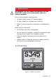
1 Operation An autopilot is a very useful navigational aid, but DOES NOT under any circumstances replace a human navigator Do not use automatic steering when: • In heavy traffic areas or in narrow waters • In poor visibility or extreme sea conditions • When in areas where use of autopilot is prohibited by law When using an autopilot: • Do not leave the helm unattended • Do not place any magnetic material or equipment near heading sensor used in the autopilot system • Verify at regular intervals c
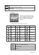
Key PWR STBY Description Power ON-OFF / Light key Standby key Engage Standby mode AUTO Auto key Engage Auto mode MODE Mode key Activate mode (soft) keys Action according to the softkey symbol TURN Turn key Enter turn sub-menu Tack or gybe in Wind mode Action according to the softkey symbol MENU Menu/Enter key Enter Main menu Enter value, Confirm, OK Left 1 key 1 Back, Left, Cancel, Exit Long press: Return to Main page (operation level 1) Adjust the commanded course or wind angle 1 degree Enable
Up key Up in menu or list box, Increase Down key Down in menu or list box, Decrease Softkeys When the basic operation of the keys is changed, softkey symbols will be displayed right above the keys to indicate the alternate function.
Operational modes The AP24 system is capable of the following primary steering modes: STBY (power steering), AUTO, NoDrift, NAV, WIND and WINDNAV. STBY and AUTO modes have dedicated keys while the other modes are available via softkeys under the MODE key. The WINDNAV mode can only be entered in WIND mode. Each mode provides you with a multifunction mode display. User adjustable settings are found in the AP24 Main menu (page 43).
A single press on the PWR key turns the autopilot system on and presents the start-up pages. • Product name • Serial number • Software version • Release date Software version and release date are examples only. After approximately 5 seconds, the system is operative and the unit that was turned on will show the Standby mode display. Other units in a multistation system will display . Control is transferred to any single unit by pressing its STBY key.
PWR a The PWR key to increase the light level by one step b The Up/Down softkeys to increase/decrease the light level by one step c The Day/Night softkeys to toggle between day and night profiles If no adjustment is performed within 3 seconds, the Light level overlay window will close. For contrast and day/night settings, refer to page 52. 1.4 Standby mode STBY mode is the mode that is used when steering the boat at the helm.
for operation of NFU steering levers or remote controls. Alternative displays in Standby mode Alternating rudder angle bargraph If your autopilot is driving a Simrad MSD50 Stern Drive, the rudder angle display will after turn-on alternate between 10 degrees port and starboard to indicate that the (rudder) zero point need be set. Refer to page 107 to set the zero point.
1.5 Automatic steering AUTO (Compass) mode When the AUTO key is pressed, the AP24 automatically selects the current boat heading as the set course and maintains the rudder angle. This gives a bumpless transfer at the mode change. • Automatic steering mode • Set course: 340 degrees • Compass reading: 340°M • Heading source: RC42 • Rudder angle: 01° to starboard • Speed: 5.
STBY • Automatic steering mode • New “captured” heading: 305° • Compass reading: 311° M (magnetic) or T (true) Regain manual steering by pressing the STBY key. Control of steering performance When operating in an automatic mode the AP24 utilizes two different sets of steering parameters (HI/LO). The parameters control the response of the boat at different speeds or wind directions.
Display legend HI-A High response parameters set automatically LO-A Low response parameters set automatically HI-M High response parameters set manually LO-M Low response parameter set manually Power boats On power boats the automatic selection of HI or LO is determined solely by the speed of the boat as shown in the diagram above. Sailboats When sailing in WIND mode, the parameter set is determined by the speed of the boat and the direction of the wind as per below.
parameter values as set by the Autotune function. If no Autotune is made (not recommended) the level 4 values are the factory default values. A low response level reduces the rudder activity and provides a more “loose” steering. A high response level increases the rudder activity and provides a more “tight” steering. A too high response level will make the boat start S-ing. When you access the RESPONSE page the highlighted Response parameter is the one that is active.
If the actual wind angle is S-ing around the set wind angle, or the rudder activity is too high, the ‘Wind response’ should be reduced. 1 MENU Range Change per step Default 1-9 1 4 Selection of HI/LO parameters 1 1 MENU The “Manual select” item has three alternatives: Auto – HI – LO.
The sub-headline in the display shows the active parameter set and how it is selected. Pattern steering (power boats) The autopilot offers a number of different pattern steering features when in AUTO mode. There is a one minute time-out between selecting a turn pattern and starting the turn. During the time-out period the autopilot will maintain the set course. When steering in a turn pattern you may at any time adjust the variables by pressing the key. To exit a turn pattern simply press the AUTO key.
C-turn makes the boat turn in a circle with a constant rate of turn. The user decides whether the C-turn should be made to port or to starboard. To enter C-turn mode: TURN or softkey to select the direction in which Press the to make the C-turn and start. The turn rate (ROT) can be adjusted before the turn is initiated and during the turn. Increasing the turn rate yields to a smaller circle and vice versa.
Spiral-turn The spiral-turn feature may also be used for circling fish or when searching a particular object on the seabed. Spiral-turn makes the boat turn in a spiral with a decreasing or increasing radius. To enter Spiral-turn mode: TURN The “initial” radius can be set before the turn is started. or softkey to select the direction in Press either the which to make the spiral-turn and start.
1 Negative values indicate decreasing radius while positive values indicate increasing radius. Increasing radius Turn parameter Initial radius Change of radius per turn Decreasing radius Range Change per step Default 33 ft - 3281 ft 10 656 ft 10 m - 1000 m 10 200 m -164 ft - +164 ft 5 66 ft -50 m - +50 m 2 20 m The unit for radius is the same as the unit set for depth (feet or meter).
Zigzag-turns To enter zigzag-turn mode: TURN The course change can be set before the turn is initiated (2-70°). Press either the or softkey to select the direction in which to make the first course change and start. While sailing in a zigzag pattern you can alter the course change, leg distance, and the main course. An arrow shows the direction of the next course change.
Initial course change 20° Main course Course change 40° Leg distance Turn parameter Range Change per step Default Course change 4° - 140° 4 28° 82 ft - 9843 ft 50 1641 ft 25 m - 3000 m 25 500 m Leg distance The unit for leg distance is the same as the unit set for depth (feet or meter). Square-turn The square-turn feature in AUTO mode can also be made as rectangle or any pattern where the next turn is 90°.
You can at any time change the main course. You can also at any time change the distance of the leg until the boat makes a new 90° turn. 1 Turn parameter Leg distance Range Change per step Default 82 ft - 9843 ft 50 1641 ft 25 m – 3000 m 25 500 m The unit for leg distance is the same as the unit set for depth (feet or meter).
Lazy S-turn To enter Lazy S-turn mode: TURN The course change can be adjusted before the turn is initiated (2-80°). Press either the or softkey to select the direction in which to make the first course change and start. While in a Lazy S pattern you can alter the course change magnitude, turn radius and the main (average) course. An arrow shows the direction of the turn.
Adjust course change and radius as follows: 1 Initial course change Main course Course change Higher radius Main course Lower radius Turn parameter Course change Radius Range Change per step Default 4° - 160° 4 28° 16 ft - 1641 ft 10 656 ft 5 m – 500 m 5 200 m The unit for radius is the same as the unit set for depth (feet or meter).
Depth Contour Tracking, DCTTM With input from an echo sounder, the autopilot can be set to steer the boat to a set depth. This is very useful if you want to follow a depth contour. Make sure you have depth reading available in the system. Smooth seabed Slope Rocky waters Narrow channel Ridge Do not use this feature unless the seabed is suitable. Do not use it in rocky waters where the depth is varying significantly over a small area. TURN The actual depth reading is shown on the display.
Steer the boat to the depth you want to track and in the direction of the depth contour (main course). When the wanted depth is shown in the display, activate the depth contour steering with the or softkey (any of the key when it is shallow to port or the two). Use the key when it is shallow to starboard. Main course This should be the main (average) direction of the depth contour you want to follow.
Contour Cross Angle (CCA) With this parameter you can make the boat lazy s across your reference depth. With the CCA set to zero there is no S-ing. The CCA is an angle that is added to or subtracted from the set course. Each time the boat crosses the reference depth, the sign (+/-) of the CCA is changed and makes the boat turn to cross the reference depth contour in the opposite direction. The larger the CCA the bigger the turn. CCA set to 15 degrees.
Tacking in Auto mode (sailboat) The tack function is only available when the system is set up for SAIL boat type in the installation setup. Tacking in AUTO mode is different from tacking in WIND mode. In AUTO mode the tack angle is fixed and can be set in the Setup/Sailing menu. Default tack angle is 100°. Tacking should only be performed into the wind and must be tried out in calm sea conditions with light wind to find out how it works on your boat.
MODE Unlike when in Auto mode the autopilot will steer the course unaffected by wind and current when the NoDrift mode is engaged. The course to steer to (bearing line) can be changed the same way as when changing course in Auto mode. • Compass heading: 345° M • Rudder Angle: 01 to starboard • Speed: 6.8 kn from the log • Steering parameter: HI-A Dodging (Resume previous bearing line) The AP24 has no specific dodge key.
the boat to a specific waypoint location, or through a route of waypoints. The information received from the navigator automatically changes the course to steer to keep the boat on the track line and direct the AP24 to the destination waypoint. If the AP24 is connected to a navigation receiver that does not transmit a message with bearing to next waypoint, it will steer on Cross Track Error (XTE) only.
The prompt display shows the name of the next waypoint (WP), the bearing of the track line (BWW) from the previous waypoint to the destination waypoint, the required course change (CHG) and the direction in which the boat will turn. If only one waypoint has been entered the bearing will be from the present position to the destination waypoint.
Press the softkey to verify course change larger than 10°. Alert screen STBY If no verification is made, the AP24 will continue on the current set course in AUTO mode. Regain manual steering by pressing the STBY key. Setting the waypoint arrival circle For route navigation it is recommended to use automatic waypoint shift at a set waypoint arrival circle. The arrival circle should be adjusted according to boat speed. The higher the speed, the wider the circle.
Example: With the speed of 20 knots you should use a waypoint circle with radius 0.09 nm. The distance between any waypoints in a route must not be smaller than the radius of the waypoint arrival circle when using automatic waypoint shift. Selecting a different navigation source If you have more than one navigator connected to the AP24, you will be able to choose any for navigation. Refer to the ‘Sources’ item in the Setup menu for details on how to select a different navigator (page 50). 1.
The wind display presents the following information: • Wind (vane) mode • Set wind angle: 010 degrees from starboard • Measured wind angle: 009°A (apparent) or T (true) • Course to steer (to maintain set wind angle): 345° • Heading: 344° M (magnetic) or T (true) • Rudder angle: 00° • Speed from log: 6.
the tack will be given by the ‘Tack time’ parameter set in the Setup/Sailing menu (page 55). The tack time is also controlled by the speed of the boat to prevent loss of speed during a tack. A quick press on the TURN key will activate the tack function and the boat will start turning to the opposite wind angle. A new press on the TURN key after the Tack window appears, will interrupt the tack operation and the boat will return to the previous set wind angle.
Tack and gybe prevent When beating and running, using the autopilot is most critical. If the sails are unbalanced when beating, yaw forces from the sails can drive the boat into the wind. If the boat is driven beyond the set minimum wind angle (see page 84), the thrust from the sails will suddenly disappear and reduces the boat speed. Hence the boat will be more difficult to steer because the rudder will become less effective.
autopilot. The autopilot will utilize the current wind direction in these calculations and the change of course is accepted by pressing the softkey [2]. Operating in WINDNAV mode Refer to Figure 1-2 which shows a scenario with a sailboat that enters WindNAV mode to sail the most efficient way to waypoint WP1. 1. The autopilot is still in Wind mode approaching mark 2 and waypoint WP1 has been entered on the chart plotter. 2.
Figure 1-2 Operation | 39
1.10 Data pages A number of data pages can be displayed if the information is available on SimNet (see page 97). When one of the main mode pages are displayed, access and scroll through the available data pages by pressing the Up/Down keys. When accessing the data pages, the last active data page will be shown first. If you prefer to change the number of instrument pages to be available; access the Main menu/Data pages setup.
Available data pages Main mode screen 1.11 Multiple station system In normal operation control is accessible from every control unit connected to the AP24 system. One control unit is "active" and provides the user with access to all functions. All remaining control units are "inactive" and have no effect on course changes. A single press on any of the mode keys on an "inactive" control unit will allow transfer of command and make it Inactive unit "active".
Blank page 42 | Operation
2 Main menu In the Main menu you will find items for operation, setup and installation of the autopilot. The Service menu item presents you with various system information and access to the Demo mode.
The Main menu is activated by a press on the MENU key. The Main menu items give further access to sub menus and parameter settings. Parameter settings are usually presented to the right, but may also be listed in an overlay window. Unit settings presented in the window’s right column Language settings presented in an overlay window.
Disabling pages 1 Continue to select pages and repeat the procedure if more pages are to be disabled. 1 Press and hold the Left 1 key to leave the menu and return to last active page. Enabling pages A disabled page is only visible when using the Enable/disable command. A disabled page is indicated with a crossed rectangle. 1 Continue to select pages and repeat the procedure if more pages are to be enabled. 1 Press and hold the Left 1 key to leave the menu and return to last active page.
Enabling all pages To restore all disabled data pages, select Restore data pages: 1 2.2 Trip log The trip log display shows: a. total accumulated distance since the instrument was installed or factory reset b. distance since the trip log was started/reset Resetting the trip log The trip log is reset to zero by pressing the Reset soft key. 2.3 User setup menu The User setup menu contains items that the user may want to use on a less regular basis.
- Adjusting the sea state filter - Changing the sailing parameters The section assumes that the user is familiar with how to use the keys and how to maneuver in the menus. If not, refer to Main menu, page 43 onwards. 1 Damping The damping factor indicates how fast the display will respond to changes. The higher the damping factor the more stable display reading on the instrument. Damping of the apparent wind angle is made by the Advanced Wind Filter (AWF) in the Autopilot Computer.
Setting Range Change per step Default Boat speed 4 Heading 1 0-9 Apparent wind 1 4 Wind shift 4 Depth 1 Alarms The AP24 may be set up to sound an alarm if vessel or environmental parameters exceeds preferred values. The alarm monitoring is disabled by setting the value to Off. Shallow water The setting of the alarm is global and can be made on any Simrad unit that has this function implemented. Range Off – 320 ft Change per step 1.6 – 5: 0.1 ft 5 – 10: 0.
Wind shift (Only available in Wind/WindNAV mode) The wind shift alarm monitors the wind angle. The reference angle is set when the alarm is turned on and when the product is turned on. The reference wind angle is reset to present wind angle when the commanded (set) wind angle is changed on the autopilot and when a wind shift alarm is acknowledged. The wind shift reading is presented on the ‘Wind shift’ data page and shows the change of wind angle with reference to the (geographic) wind direction.
The data types and their respective data sources used in the products are listed on the source page in the products. If no selection is made for a data type, ‘- - -‘ is displayed instead of the device name or acronym. SimNet will automatically select Position source and Navigation source from the same GPS/chart plotter. If you want them to be different you have to change them manually.
list. Highlight the data type and press the display the list of available devices. 1 key to Confirm selection of the highlighted device. Exit without selecting See information about the selected data source. For data types which can be calibrated, an overlay screen displaying the data from the selected data source will appear first (Ref. Installation/Calibration). Enter the Calibrate and Offset menu. (Ref. Installation/Calibration).
Display The display is controlled by two user profiles that can be individually adjusted. The profiles are Day profile and Night profile. The profiles can be optimized for readability under different light conditions, and you can quickly switch between the two using the PWR key and the Backlighting, page 9. softkeys.
Language The language is set when the autopilot is turned on for the first time. Refer First time turn on, page 59. It is however possible to change the language at any time. The following languages may be selected: - Deutch (German) - English (English) - Español (Spanish) - Français (French) - Italiano (Italian) - Nederlands (Dutch) - Norsk (Norwegian) - Svenska (Swedish) The language names are listed alphabetically in their own language.
Units of measure Parameter Boat speed Options − kn Default kn − km/h − mph Wind speed − kn kn − m/s − mph Distance − nm nm − km − mi Depth − m ft − ft Heading − °M °M − °T Temperature − °C °F − °F The display unit for heading data is not solely determined by the user. If true heading is wanted but the selected compass is a magnetic compass, then the magnetic variation must be available from a position- or navigation source.
Sea state filter The Seastate filter is used to reduce rudder activity and autopilot sensitivity in rough weather. OFF: Seastate filter is disabled. This is default. AUTO: Reduces rudder activity and autopilot sensitivity in rough weather by an adaptive process. The AUTO setting is recommended if you want to use the Seastate filter. MANUAL: Linked to the Response control setting in the Main menu.
Tack time When performing a tack in WIND mode, the rate of turn (tack time) can be adjusted. This will give single-handed sailors time to handle the boat and the sails during a tack. A turn performed without shifting wind side, will also be made at a controlled turn rate. Range Change per step Default Units 2 - 50 1 12 second Tack angle AUTO In AUTO mode the set tack angle replaces a similar change of the set course using the starboard and port keys.
VMG optimizing Optimizing the VMG to wind will be active for 5–10 minutes after a new wind angle has been set and only when beating. ‘VMG’ will be displayed in the upper left corner above the mode index when the VMG optimizing feature is active. Range Default Off - On Off Layline steering Layline steering is useful when navigating. Cross Track Error (XTE) from the navigator will keep the boat on the track line. If the XTE from the navigator exceeds 0.
On the active control unit a the mode index.
3 Setup at installation 3.1 First time turn on Before attempting to turn on the AP24 and perform an Installation Setup, the hardware installation and electrical connections must be completed in accordance with the installation instructions.
3.2 Installation Menu The installation settings must be performed as part of the commissioning of the AP24 system. Failure to do so correctly may prohibit the AP24 from functioning properly! The Installation menu can only be accessed in STBY mode.
Commissioning 1 Dockside settings 1 If the autopilot has no rudder feedback unit installed refer to Virtual Rudder Feedback on page 70-72. The following menu items are accessible and can be set up in the Dockside menu: - Boat type - Rudder feedback - Virtual feedback - Drive voltage - Drive engage - Rudder test - Depth calibration - Minimum wind angle - Nav change limit Not applicable for EVC! (ref.
Confirm by pressing the softkey. Rudder feedback calibration (Not applicable for EVC) Make sure the unit is installed and aligned as per instruction in the AC12/42 Installation manual. The rudder feedback calibration will set the correct relationship between the physical rudder movement and the rudder angle readout. 1 Manually turn the helm/wheel to starboard until the rudder stops at starboard lock (H.O.).
1 Manually turn the helm/wheel to port until the rudder stops at port lock (H.O.). Adjust the displayed angle the same way as for starboard rudder. MENU Confirm Rudder feedback calibration to port by pressing the MENU key. Many boats have ±45° (90° H.O. - H.O.) rudder angle as standard. So if you are not going to make any adjustment to the displayed angle you should still highlight the reading and confirm. This is necessary to prevent the rudder from hitting the end stops.
Special test of LF3000/LFI3000 Mk2 feedback 1 Align engines to center position; “zero rudder”. 2 Rev engines to 3-4000 rev/min and observe the rudder angle indicator on the autopilot, a 2° change in the reading should be accepted. 3 If the rudder angle exceeds 2°, connect the screen on the TB1 cable (LFI3000) to the center block terminal and repeat item 2 (Refer to the AC12/AC42 Installation manual). If this gives a better result keep the screen connected.
The drive engage/bypass clutch output follows the same voltage as set for the drive unit. It is not possible to select a higher voltage than the supply voltage. Selection of improper voltage level for your drive unit may damage both the drive unit and the autopilot computer even if the protection circuits in the autopilot computer are activated. The drive unit voltage setting does not apply when operating solenoids on a continuous running pump.
‘Drive engage’ port will activate (go high) in all active steering modes, and typically engage a bypass valve on a hydraulic linear drive or a clutch on a mechanical drive. Auto: This setting is implemented for future use. Always use the “Clutch” (default) setting. Rudder Test (Not applicable for EVC) If the boat uses power assisted steering, it is important that the engine or electric motor used to enable the power assist steering be turned on prior to this test.
Depth calibration This adjustment only applies to “smart” depth transducers that outputs depth on NMEA2000 format. The default value for the depth offset is 0.0, which indicates the displayed depth from the transducer to the seabed (b). Refer to the illustration on next page.
The symbol in front of the depth reading will change to indicate that the depth is measured from: the keel Range -10 - +10 or Step 0 – ±5: 0.1 5 – 10: 0.5 the water line Default Units 0.0 m, ft Press the MENU key to confirm the offset setting.
Minimum wind angle Minimum wind angle is only available if ‘Boat type’ is set to ‘Sail’ in the Installation menu. The ‘Minimum wind angle’ is the minimum apparent wind angle that will keep the sails well shaped and give an acceptable thrust. This parameter will vary from boat to boat. The ‘Minimum wind angle’ applies for the tack-prevent function. It also applies when the autopilot is operating in WindNAV mode. You can select different minimum wind angles for port and starboard.
The ‘Nav change limit’ screen can also be reached from the Nav mode main screen by pressing the MENU key followed by the MODE key within 2 seconds. Range Change per step Default Units 10 - 30 10 10 ° Dockside settings when using Virtual Rudder Feedback The Virtual Feedback algorithms in the autopilot software enable your autopilot to steer without a conventional rudder feedback unit. These algorithms are designed for vessels up to 40 ft. powered by outboard or stern drives only.
Boat type 1 When the autopilot is configured for Virtual Feedback the Boat type is automatically set to Outboard. Rudder Feedback (calibration) (Not applicable for VRF) (Default values +/-35° are used) Refer to pages 64-65 to set the Drive unit voltage and the Drive Engage. Rudder test To perform the Virtual Feedback rudder test you must be able to view the movement of the engines/drives (“rudder”). Activate the automatic rudder test as shown, following the instructions on the display.
Continue to follow the instructions on the display. With the rudder hard over to starboard, turn the wheel carefully a little to port to release the hydraulic pressure. Confirm by pressing the softkey. Immediately release the softkey when the rudder reaches the hard over position. The rudder will now be automatically centered. B The Rudder test is verified by the display showing ‘Motor OK’ or ‘Failed’. If ‘Failed’ is given, check for correct electrical connection.
Seatrial settings The Seatrial menu presents settings and automatic calibrations to be performed during seatrial. The seatrial must always be performed in open waters at a safe distance from other traffic. The Seatrial menu can only be accessed if the Dockside Settings are completed and confirmed.
The calibration should be done in calm sea conditions and with minimal wind to obtain good results. Use about 6090 seconds to make a full circle. 1. Highlight the Calibrate line in the dialog 2. Begin turning the boat to port or starboard 3. Press the MENU key to start the automatic compass calibration a. An information window will be displayed when the calibration procedure is running. b. The digits below the bargraph will read 0.0 when the turn rate is correct.
1 Calibration is made on the compass that is active for the autopilot. 2 If another model compass from Simrad or another manufacturer is installed, refer to the instruction for that compass regarding calibration. Lubber line Lubber line Magnitude of local field in % of earth’s magnetic field. Direction of local field with respect to lubber line. It can also be on the reciprocal.
1 4 Confirm the Offset by pressing the MENU key Wind Calibration This calibration only applies if you have a wind transducer directly connected to SimNet (IS12TW) or a wind transducer that outputs data on NMEA2000 format. Any residual error in the apparent wind angle display can be corrected manually by entering the required offset. A positive value indicates starboard offset angle,- a negative value indicates port offset angle.
Boat speed calibration The hull shape or the location of the speed sensor may cause incorrect speed readings, and it may be required to calibrate the input to ensure that correct speed and log values are displayed. Calibrate by Speed Over Ground With a GPS connected to the system, the speed through water (SPD) can be calibrated equal to Speed Over Ground. This adjustment should be made in calm sea with as little wind or tidal current as possible.
Transition HI-LO The Transition HI-LO is the speed at which the AP24 will automatically change the steering parameter set from HI to LO parameters, or vice versa (page 13). The default setting of the Transition speed is 6 knots. On power boats it is recommended that you set the Transition HI-LO to a speed that represents the speed where the hull begins to plane or the speed where you change from slow to cruising speed.
The automatic tuning process is also verifying/adjusting the “Rudder zero” alignment made in Dockside setup. Automatic tuning is a procedure that is not required for the AP24 to function as it is preset with steering parameters that should steer most boats in the 30 - 50 foot range. Recommended speed during Automatic tuning should not exceed 10 knots. It should be performed in calm or moderate sea conditions, preferably when steering East or West.
Status The Status screen shows a list of installation items to be done and installation items completed. 1 Return to the Installation menu item ‘Automatic steering’ if you want to adjust the steering parameters. See below for information. Automatic steering The Automatic steering menu contains steering parameters for course steering, wind steering and nav steering.
Manual tuning The steering parameters can be looked at and changed if needed under this menu item. The parameters are divided into two sets (page 16): • HI value parameters for automatic steering at low speed and when running with a sailboat • LO value parameters for automatic steering at high speed and when sailing into the wind or reaching with a sailboat The ‘Manual tuning’ screen can also be reached from the Auto mode main screen by pressing the MENU key followed by the MODE key within 2 seconds.
The values in the table are factory set (default) and listed for information only. After having performed the Autotune, the values may differ from those listed in the table. See also “Autotune” previously in this chapter. The two most important parameters that determine the performance of the automatic steering are Rudder and Counter Rudder. Rudder sets the rudder gain which is the ratio between the commanded angle and the heading error.
New course Counter rudder setting too low, overshoot response New course Counter rudder setting too high, sluggish and creeping response New course Correct setting of counter rudder, ideal response Autotrim standard value is 40 seconds which should work well on most boats. Rule of thumb: Set to same value (seconds) as the boat’s length in feet. On boats operating on VRF it should be set to 20 seconds. Rate Limit should be kept at 6.0°/second unless there is a need for more rapid response in turns.
During the seatrial, only set Minimum Rudder to ON if it proves to give a better course keeping performance in calm sea. It should be set after the Autotune has been performed and a possible fine tune of the Rudder parameter (page 82). Range Change per step Default Units OFF - 5 0.1 OFF ° Final seatrial After having completed all settings in the Installation Menu, take the boat out and perform a final seatrial in open waters at a safe distance from other traffic.
• If the boat is a sailboat use the WIND mode and try the AP24 at different settings of the apparent wind angle. Also try the WINDN(av) mode, optimized VMG and WCV when sailing (tacking) to a waypoint • If the rudder response feels aggressive during the seatrial, you may want to reduce the rudder speed to get a smoother steering. Alternatively on a sailboat you may want to have a higher rudder speed when running • The motor Drive out (page 86) can be set with the above in mind.
• Understand the difference between NAV mode and NoDrift mode and their data sources (Nav, Pos) • Locating compasses and knowing to keep magnetic items away • Locating the Mains circuit breaker and the separate SimNet circuit breaker if provided Calibration The Calibration is another entry to procedures for calibrating the compass, rudder feedback, depth, apparent wind angle and boat speed. These procedures are covered under ‘Commissioning’.
If the auto-setting does not perform properly due to high inertia from the wheel or a loose steering gear, it can be adjusted manually. Find the lowest possible value that will prevent the rudder from continuous hunting. A wide deadband will cause inaccurate steering. It is recommended to check rudder stability in AUTO mode when the boat is moving to get pressure on the rudder. Range Change per step Default Units AUTO, 0.1 – 4.0 0.
SimNet configuration SimNet units can be assigned in groups and given an instance number for identification. SimNet Groups The SimNet group function is used to globally control parameter settings in groups of units. The function is used on larger vessels where several units are connected via the SimNet network. By assigning several units to the same group, a parameter update on one unit will have the same effect on the rest of the group members.
- Simrad: Default group for AP24 - None: Not assigned to a group - 1–6: Group numbers The figures on next page illustrates how the instruments on a flybridge and in a cockpit are assigned to separate language, damping and backlight groups, and how this affects the setup for the different instruments.
Instance number The instance number is used to identify multiple units of the same model when connected to a SimNet or NMEA2000 network. The instance number is added to the product name e.g. AP24-1, AP24-2 for easy identification of the unit. Range Step Default value 0 - 20 1 0 3.3 Service Information Also see Trouble shooting page 97 about SimNet status, System data and resets.
Confirm Demo mode by pressing the softkey. If the unit is turned off while in demo mode, the demo mode will still be active on next power on. Demo mode is deactivated by using the menu as illustrated above. An automatic source update is then initialized. The user will be notified with a ‘DEMO’ message every 1 second as long as the demo is running. To have the full benefit of the autopilot in Demo mode, an Autopilot Computer must be part of the system.
Blank page 92 | Alarm system
4 Alarm system 4.1 Alarm indication The alarm system in the AP24 autopilot is activated if any alarm settings are exceeded. Refer to Alarms, page 48. When an alarm is notified, the alarm will be indicated with an alarm text and with an audible alarm. The different alarm indications are shown in the table below.
4.2 Acknowledging an alarm An alarm is acknowledged by pressing any key. This will remove the alarm notification (text, light and sound) from all units that belongs to the same alarm group. Refer to SimNet Groups, page 88. A reminder will reappear at given intervals as long as the alarm situation exists. An alarm received from other SimNet units must be rectified on the unit generating the alarm! 4.3 Viewing active alarms A list of any existing alarm condition may be displayed at any time. 4.
Alarm ID Alarm 10 Shallow water 11 Deep water 12 Anchor alarm 13 Wind shift 14 True wind speed too high 15 True wind speed too low 16 Boat speed too low 17 Voltage too high 18 Voltage too low 19 Depth data missing 20 Wind data missing 21 Nav data missing 22 Compass data missing 23 Off course 24 Rudder data missing (RF25) 25 Rudder feedback failure (RF300) 26 Rudder response failure 27 Drive overload 28 High temperature 29 Bypass/clutch overload 30 Bypass/clutch dis
Blank page 96 | Alarm system
5 Troubleshooting An autopilot is a complex system. Its performance depends on a proper installation and a successful seatrial. The Main menu includes a Service item that access several options to display data used when testing or troubleshooting the system. 5.1 SimNet status The SimNet status screen provides you with status information about the different SimNet messages used by the system. 5.
5.3 Resets Autopilot reset An Autopilot Reset is part of the final test at the factory, which will reset the memories to factory settings. Unless you need to clear all stored values during the installation setup, you should not perform an Autopilot reset. 1 To confirm the autopilot reset press the softkey. The Installation and Setup procedures must be repeated after a reset has been performed! In the event an Autopilot reset has been made, refer to chapter 3.2.
Autopilot failures In the event of an autopilot failure, the AP24’s numerous test features will assist you in isolating a probable fault. Audible and visual alarm are provided for every fault being detected, see chapter 4. Refer to the table below for hints and try to solve the problem yourself. You may also consult your nearest Simrad dealer for assistance, if required. Perform any repair action in the listed sequence. 1 The ‘Off course’ warning is automatically reset when the error is rectified.
Display readout Shallow water Probable fault Recommended action The depth is inside the set limit or outside the range Carefully observe the actual depth Depth data is missing Adjust the alarm limit if not hazardous Steer to safe depth, the alarm will reset automatically Turn off the shallow alarm if data is missing Compass data missing No data from selected compass If more that one compass is connected to the system, refer to the Setup/Sources menu to select a different compass Make a source updat
Display readout Rudder test failed Probable fault Following conditions may exist: Recommended action Refer to recommended actions for the specific probable faults Rudder feedback failure Autopilot computer current overload Bypass/clutch overload Rudder moves in only one direction Check the connections Poor connection to one of the solenoids (continuously running pump) Replace the autopilot computer Faulty PCB in autopilot computer Rudder test not completed within 2 min.
Display readout Bypass/clutch overload Probable fault Clutch/bypass current exceeds 3.3 Amps (overload or short circuit). Recommended action Check actual current Check voltage marking on coil Check coil resistance (through connecting wires) Bypass/clutch disengaged Poor connection or open circuit in bypass/clutch coil Check connections Replace bypass/clutch if open Perform new "Rudder test" ACXX High temperature Excessive temperature in autopilot computer (>80°C), possible long term overload.
6 Maintenance 6.1 General The AP24 units are “repair by replacement” units, and the operator is therefore required to perform only a very limited amount of preventive maintenance. 6.2 Control unit The AP24 Control Unit will under normal use require little maintenance. If the unit requires any form of cleaning, use fresh water and a mild soap solution (not a detergent). It is important to avoid using chemical cleaners and hydrocarbons such as diesel, petrol etc.
6.5 Compass If the compass is exposed to the weather, make a visual inspection at 2-3 months intervals, and at the start of each season. 6.6 Drive unit Refer to the drive unit manual for maintenance instructions. 6.7 Exchange of software program Contact Simrad Customer Support about software updates.
7 Optional equipment 7.1 R3000X Remote Control (NFU) R3000X is a small handheld remote control with two keys for power steering or course selection (port and starboard), and one key with a LED indicator for (limited) mode change. Operation SIMRAD STBY-AUTO Push key for Port and Stbd commands STBY/ automatic. Automatic modes are active when the lamp is lit. Simrad R3000X In STANDBY mode, the rudder will move for as long as the Port or Stbd key is pressed.
7.2 S35 Steering Lever (NFU) S35 has spring-loaded return to mid-position. A push key with light indicator is used for mode selection similar to the R3000X Remote Control. Alternatively S35 can be used as a conventional NFU lever without mode selection. Operation Refer to the operation of the R3000X in the previous chapter. On S35 you move the lever to right or left instead of using keys. 7.
Zero point setting Unless you need a rudder angle display when leaving the dock, just steer the boat manually on a straight course and press the AUTO key. The zero point is then set automatically. If you prefer to use the rudder angle display when leaving the dock, proceed as follows: After turn-on the rudder angle display will alternate between 10 degrees port and starboard to indicate that the (rudder) zero point need be set. Turn the wheel from lock to lock (H.O. to H.O.
Blank page 108 | Optional equipment
8 Glossary Apparent wind – The speed and direction from which the wind appears to blow with reference to the bow when the boat is moving (also called relative wind). Arrival alarm – An alarm signal issued by a GPS/chart plotter that indicates arrival at or at a predetermined distance from a waypoint (see arrival circle). Arrival circle – An artificial boundary placed around the destination waypoint of the present navigation leg, the entering of which will signal an arrival alarm.
Magnetic bearing – Bearing relative to magnetic north; compass bearing corrected for deviation. Magnetic deviation – A local magnetic field on board a vessel. Can interfere with the earth’s magnetic field and create compass readings that may deviate from the actual magnetic heading. The deviation will vary with the actual heading. Magnetic heading – heading relative to magnetic north. Magnetic variation - A magnetic compass points to the magnetic north pole.
SimNet Class 1 products – Simrad products that are SimNet controllers, i.e. they have an appropriate display and routines that can set up and control the SimNet. SimNet Class 2 products – Simrad products that do not contain a SimNet controller. When connected to SimNet they will automatically pick the first available source on SimNet and lock onto that. When a Class 1 product is added to the Simrad Group, Class 2 products will automatically subordinate themselves to the Class 1 source selection.
Blank page Glossary | 112
9 Index A about, 91 alarm codes, 95 indication, 93 listing, 99 shallow water, 48 wind shift, 49 apparent wind, 56, 109 apparent wind angle, 76 arrival circle, 33 automatic tuning, 78, 79 autopilot computer maintenance, 103 autotrim, 83 depth contour tracking, 26 depth gain, 27 dockside settings, 61 dodging, 30 drive engage, 65 drive unit maintenance, 104 voltage, 64 E EVC, 11, 95, 109 F failure, 99 G B backlighting, 9, 52 boat type, 61 C calibration apparent wind angle, 76 boat speed, 77 compass,
N nav change limit, 32, 69 navigating, 31 NFU Steering lever, 106 NoDrift, 29 P software program, 104 speed over ground, 77 spiral-turn, 19 square-turn, 22 status, 80 symbols, 7 system data, 97 parameter selection T automatic, 13 pattern steering, 17 power steering, 10 R rate limit, 83 recall autotuned, 80 reference depth, 28 remote lock, 57 reset tack angle, 56 tack time, 36, 56 tacking in auto mode, 29 in wind mode, 35 transition HI-LO, 13, 78 transition speed, 78 trip log, 46 true bearing, 11
AP24 manual EN, Doc.no.20222535, Rev.