
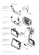
Installation Instructions


|
19
Connecting power | NSS Installation Manual
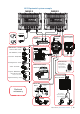
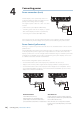
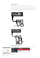
12 - 24 V DC
Red
Black
Power Control Master
Power Control Slave
Boradband Radar
Yellow
Red
Black
Yellow
Red
Black
Power Control Bus
Yellow
+
_
AB
C
Power Control Master
Display (A) turns on using the power button. It is set as the Power Control Master and will
output voltage on the Power Control bus to turn on display (B) and Broadband radar (C).
Display (B) is set to Power Control Slave and if turned on by display (A) cannot be powered
down using its own power button, but can be set to standby.
If display (A) is o , display (B) can be turned on using its power button, but won’t turn on
any other devices. Display (B) could, however also be set to Power Control Master.
Note: If a display has its power state controlled by another display or ignition switch, it can’t
be totally powered down. It can enter a standby state to save power. If the power button is
pressed and Power O selected, a message will appear “Preparing to standby…”
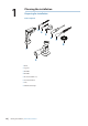
Power Control setup
To con gure a display as a Power Control Slave or Master select Power control from the
‘Settings’ menu.
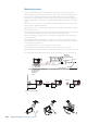
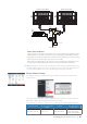
The following Simrad products require (+) DC Volts on the yellow wire in order to function:
NEP-2, BSM-1, BSM,-2, WM-2, Broadband radar, RI10, SonicHub.
The +DC volts can come via a switch, a breaker or from an NSS or NSE display yellow wire.
Not connected Fused + DC power
supply
Switch NSS, NSE display
yellow wire
Unit is turned on
using the power key
Unit always on when
power is on
Unit power con-
trolled by switch
Unit turned on or o
by display (if display
power control master)